Centrifugal Compressors
920 likes | 2.81k Vues
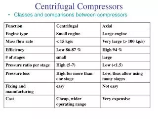
Centrifugal Compressors. Classes and comparisons between compressors. Centrifugal Compressors. Principle of Operation Centrifugal compressors consist of stationary casing containing Rotating impeller (imparts a high velocity of air),

Centrifugal Compressors
E N D
Presentation Transcript
Centrifugal Compressors • Classes and comparisons between compressors
Centrifugal Compressors • Principle of Operation • Centrifugal compressors consist of stationary casing containing • Rotating impeller (imparts a high velocity of air), • Fixed diverging passage (The air is decelerated with rise in static pressure). • Impeller may be single or double-sided
Centrifugal Compressors • Air is sucked into the impeller eye and whirled at high speed by the vanes of the impeller disc. • The static pressure increases from eye to tip. • Remainder of static pressure rise occurs in diffusers. • Normally half of pressure rise occurs in the impeller and 50% in diffuser. • Some stagnation pressure loss occurs.
Centrifugal Compressors • Work done and Pressure Rise: • Absolute velocity of air at impeller tip. • tangential or whirl component • radial component. • is the angle given by the direction of the relative velocity at inlet V1. Also this is the angle of leading edge of the vane with tangential direction. • Slip phenomenon: air trapped between the impeller vanes does not move with the impeller, thus air acquire whirl (Cw) velocity at the tip which is less than u. • :
Centrifugal Compressors • Velocity diagrams
Centrifugal Compressors • Considering unit mass of air: • momentum equation
Centrifugal Compressors • With state 1 as inlet to rotor • “ 2 as exit from rotor • “ 3 as exit of diffuser • No energy addition in diffuser • Thus =
Centrifugal Compressors • Defining c as overall isentropic efficiency, then overall stagnation pressure ratio is given by :
Centrifugal Compressors • Example 4.1 • The following data are suggested as a basis for the design of a single-sided centrifugal compressor: • Power input factor = =1.04 • Slip factor = 0.9 • Rotational speed, N= 290 rev/s • Overall diameter of impeller, D=0.5m • Eye tip diameter=2re=De=0.3m • Eye root diameter, D1=2r1=0.15m • Air mass flow, m=9 kg/s • Inlet stagnation temperature To1= 295 • Inlet stagnation pressure Po1 = 1.1 bar • Isentropic efficiency, c=0.78
Centrifugal Compressors • Requirements are • (a) to determine the pressure ratio of the compressor and the power required to drive it assuming that the velocity of the air at inlet is axial. • (b) to calculate the inlet angle of the impeller vanes at the root and tip of the radii of the eyes, assuming that the axial inlet velocity is constant across the eye annulus; and • (c) to estimate the axial depth of the impeller channels at the periphery of the impeller.
Centrifugal Compressors • (a) impeller tip speed • Temperature equivalent of the work done on unit mass flow of air, is
Centrifugal Compressors • Power required= (b) to find the inlet angle it is necessary to determine the inlet velocity which in this case is axial; . Since the density 1 depends upon C1and both are unknown, a trial and error process is required.
Centrifugal Compressors • Flow triangles • u2=455.5 m/s • Assume axial flow • two unknown (,c) in one equation but another relation is given by
Centrifugal Compressors • Note this is normal to design for an axial velocity of about 150 m/s, this providing a suitable compromise between high flow per unit frontal area and frictional losses in the intake. • Annulus area of impeller eye, Based on stagnation conditions:
Centrifugal Compressors , the equivalent dynamic temperature is
Centrifugal Compressors equivalent dynamics temperature is
Centrifugal Compressors • This is a good agreement and a further trial using Ca1=143 m/s is unnecessary because a small change in C has little effect upon . • For this reason, it is more accurate to use the final value 143 m/s, rather than the mean of 145 m/s ( the trial value) and 143 m/s. • The vane angles can now be calculated as follows: and at eye root radius =136.5 m/s,
Centrifugal Compressors • at root=tan-1(143/136.5)=46.33, • at tip =tan-1143/273=27.65 (c) the shape of the impeller channel between eye and tip is very much a matter of trial and error. The aim is to obtain as uniform a change of flow velocity up the channel as possible, avoiding local decelerations up the trailing face of the vane. To estimate the density at the impeller tip, the static pressure and temperature are found by calculating the absolute velocity at this and using it in conjunction with the stagnation pressure which is calculated from the assumed loss up to this point.
Centrifugal Compressors To calculate density at exit
Centrifugal Compressors thus get 2.
Centrifugal Compressors The required area of cross-section of flow in the radial direction at the impeller tip is
Computational Design of a Centrifugal Compressor • PROGRAM MAIN • COMMON CP,R,GAMRAT • COMMON VECT(5000,500) • C • C • C OPEN(30,FILE='D:\Dif\GRIDG.RES') • OPEN(5,FILE='C:\CALCULATIONS\Data_PyT10_6.1mps_D50mmFdn.txt') • OPEN(6,FILE='C:\CALCULATIONS\OUT.txt') • OPEN(7,FILE='C:\CALCULATIONS\output data for drawings.txt') • OPEN(8,FILE='C:\CALCULATIONS\OUT2.txt') • C OPEN(30,FILE='C:\Dif\GRIDG.RES') • C OPEN(6,FILE='C:\Dif\Conv 1\GRIDG.OUT') • C OPEN(5,FILE='C:\dif\Conv 1\GRIDG.DAT') • C OPEN(30,FILE='C:\Dif\Conv 1\GRIDG.RES',FORM='UNFORMATTED') • C OPEN(6,FILE='C:\Dif\GRIDG.OUT') • C OPEN(5,FILE='C:\dif\GRIDG.DAT') • C OPEN(6,FILE='D:\Dif\GRIDG.OUT') • C OPEN(5,FILE='D:\dif\GRIDG.DAT')
Computational Design of a Centrifugal Compressor • C • PI=22./7. • EPSI=1.05 • SIGMA=0.9 • RPM=305. • D0=0.6 • DIT=0.4 • DIR=0.15 • FLOW=14 • TO1=300 • PO1=100. • EFFC=0.8 • CP=1005 • EFFIMP=0.89 • GAMMA=1.4 • R=0.287 • GAMRAT=GAMMA/(GAMMA-1.) • U=PI*D0*RPM • TO13=EPSI*SIGMA*U*U/CP • PO13=(1.+EFFC*TO13/TO1)**GAMRAT • TO3=TO1+TO13 • TO2=TO3 • PO3=PO1*PO13 • POWER=FLOW*CP*TO13/1000. • WRITE(6,11)POWER,TO13,U,PO13 • 11 FORMAT(2X,'POWER=',E13.4,/2X,'TO13=',E13.5/2X,'U=',E13.5/3X, • 1'Press ratio=',E13.4//) • AI=PI*(DIT**2-DIR**2)/4.
Computational Design of a Centrifugal Compressor • C • C1=100. • CALL SITER(C1,TO1,PO1,AI,FLOW) • CWRITE(6,12)C1,EPS,P1,T1,AI • C 12 FORMAT(2X,E13.3/4E13.4) • UE=PI*DIT*RPM • UR=PI*DIR*RPM • ALFAR=ATAN(C1/UR)*180./PI • ALFAT=ATAN(C1/UE)*180./PI • WRITE(6,24) • 24 FORMAT(8X,'ALFAT, ALFAR'/) • WRITE(6,13)ALFAT,ALFAR • 13 FORMAT(2X,2E13.3) • C • CAxial DepthCR=C1 • CW=SIGMA*U • CSQ=CR*CR+CW*CW • PO2=PO1*(1.+EFFIMP*TO13/TO1)**GAMRAT • T2=TO2-CSQ/(2.*CP) • P2=PO2*(T2/TO2)**GAMRAT • RHO2=P2/(R*T2) • A2=FLOW/(RHO2*CR) • AXDEPTH=A2/(PI*D0) • WRITE(6,17)AXDEPTH • 17 FORMAT(//10X,'Axial Depth= ', 10X, E13.5)
Computational Design of a Centrifugal Compressor • C • C CALL PERFORMANCE(POWER,TO1,PO1,EFFC,GAMRAT,CP) • STOP • END • C • SUBROUTINE SITER(C,TO,PO,A1,FLOW) • COMMON CP,R,GAMRAT • C WRITE(6,102)C,EPS,PO,TO,A1 • RHO1=PO/(R*TO) • 10 C=FLOW/(RHO1*A1) • T=TO-C*C/(2.*CP) • P=PO*(T/TO)**GAMRAT • C • 23 FORMAT(7X,'C',18x,'EPS',8X,'P',8X,'T',15X,'A1'/) • C WRITE(6,102)C,EPS,P,T,A1 • RHONEW=P/(R*T) • EPS=ABS((RHONEW-RHO1))/RHONEW • IF(EPS.LT.0.001)GO TO 20 • RHO1=RHONEW • GO TO 10 • 20 CONTINUE • WRITE(6,23) • WRITE(6,102)C,EPS,P,T,A1 • 102 FORMAT(2X,5E13.4/) • Return • End
Computational Design of a Centrifugal Compressor • SUBROUTINE PERFORMANCE(POWER,TO1,PO1,EFFC,GAMRAT,CP) • COMMON VECT(5000,500),WMAS(5000,500),BETA(5000,500),PI • FLOW=10. • DFLOW=FLOW/10. • WRITE(6,30)POWER,TO1,PO1,EFFC,GAMRAT,CP • 30 FORMAT(6E13.3) • DO 10 I=1,9 • TO3=TO1+POWER*1000./FLOW/CP • PO3=PO1*(1.+EFFC*(TO3-TO1)/TO1)**GAMRAT • FLOW=FLOW-DFLOW • CWRITE(6,20)TO3,PO3 • WRITE(6,20)FLOW,PO3/PO1 • 20 FORMAT(2E13.3) • 10 CONTINUE • C • RETURN • END
Centrifugal Compressors • The Diffuser: • In the case of gas turbine, the air should exit the diffuser and enters the combustion chamber at minimum velocity. • Thus, design of diffuser requires that only a small part of strengthening temperature is K.E. normally u=90m/s at exit of the compressor. • rapid divergence is not recommended • optimum angle is 7.0. • Neglecting losses, thus, angular momentum r C=constant • Cr: radial velocity will also decrease.
Centrifugal Compressors Example 4.2Consider the design of a diffuser for the compressor dealt with in the previous example. The following additional data will be assumed:Radial width of vaneless space wd = 5 cmApproximate mean radius of diffuser throat, rm =0.033m Depth of diffuser passages dd 1.76Number of diffuser vanes nv 12Required are (a) the inlet angle of the diffuser vanes and (b) the throat width of the diffuser passages which are assumed to be of constant depth • Consider conditions at the radius of the diffuser vane leading edges, at r2=0.25+0.05=0.3m. Since in the vaneless space r Cw =constant for constant angular momentum,
Centrifugal Compressors The radial component of velocity can be found by trial and error. The iterationmay be started by assuming that the temperature equivalent of the resultant velocity is that corresponding to the whirl velocity, but only the final trial is given here.
Centrifugal Compressors • Ignoring any additional loss between the impeller tip and diffuser vane leading edges at 0.3m radius, the stagnation pressure will be that calculated for the impeller tip, namely it will be that given by
Centrifugal Compressors • Area of cross-section of flow in radial • Check on Cr2: • Cr2=Taking Cr as 97.9 m/s, the angle of the diffuser vane leading edge for zero incidence should be
Centrifugal Compressors • the throat width of the diffuser channels may be found by a similar calculation for the flow at the assumed throat radius of 0.33m. Try Cr2= 83 m/s
Centrifugal Compressors • Area in radial direction=A (radial) = 2Db =0.0365
Centrifugal Compressors • Compressibility Effects • At the impeller inlet,( eye of the impeller), the relative velocity is high and could be very close to sound values. No problem at sea level conditions, however at high altitude ( aircraft engine), speed of sound decreases and we might have supersonic flow. For example at 11000 m, T=217 K
Centrifugal Compressors • we try to avoid this by having guide vanes and it is better to be variable in the case of change of conditions, such as altitude. • By trial and error, the value of Ca can be determined from Ca and , C1t 9and C1t can be determined. Then value V1t9can be determined which is smaller.=239 m/s. For this design, the flow is subsonic at altitude. Trying
Centrifugal Compressors • For 30 pre whirl • C1=150/cos30=173.2
Centrifugal Compressors • In spite of the advantage, it has a disadvantage of reducing the pressure ratio of compressor.
Centrifugal Compressors for details see text book
Centrifugal Compressors • Vaneless diffusers: • For vaneless diffuser, no problem, it can handle supersonic flow while vaned diffuser can’t. • At the exit of the vaneless diffuser, C3=355, M2=0.56<1.0, which is subsonic and is ok for vaned diffuser. • Advantages of vane less diffuser: • Mach number M2 could be supersonic without • Vaneless space will eliminate any non-uniformity of the flow coming out of the impeller ( jets and wakes). • This is good to avoid any problem in exciting the vanes. • As a normal practice, no. of vanes in the diffuser is less than impeller blades. • N (vanes)<N (impeller)
Centrifugal Compressors • Non-dimensional quantities for compressor characteristics: • D=diameter, N=rpm, m=mass flow rate • po1=inlet pressure, po2=exit pressure • T01=inlet temperature, To2=exit temperature • N=no. of variables • M=basic dimensions • there are 7 variables, 3basic dimensions (M,L,T) • and terms 7-3=4.
Centrifugal Compressors • Stall • Defined as the (aerodynamic stall) or the break-away of the flow from the suction side of the blades. • A multi-staged compressor may operate safely with one or more stages stalled and the rest of the stages unstalled . but performance is not optimum. Due to higher losses when the stall is formed. • Surge • Is a special fluctuation of mass flow rate in and out of the engine. No running under this condition. • Surge is associated with a sudden drop in delivery pressure and with violent aerodynamic pulsation which is transmitted throughout the whole machine.