Download
1 / 63
630 likes | 867 Vues
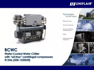
BCWC Water-Cooled Water Chiller with “oil-free” centrifugal compressors R134a (320-1250kW). UpCO3m + UG40 MICROPROCESSOR CONTROL. Overview. UpCO3m microprocessor control board to which all input and output devices are connected. UG40 User Interface. Status Masks.

E N D
BCWC Water-Cooled Water Chiller with “oil-free” centrifugalcompressors R134a (320-1250kW)
UpCO3m + UG40 MICROPROCESSOR CONTROL
Overview UpCO3m microprocessor control board to which all input and output devices are connected UG40 User Interface
Status Masks The unit’s operating parameters (temperatures, humidity…) can be consulted by scrolling through the screens with the UP and DOWN keys. When the consultation cycle ends, the initial STATUS SCREEN returns. Press the ESC key to go directly to the STATUS SCREEN. From the main screen press the Down key and a sequence of data will appear on the screen. Screen displaying readings for the cold water evaporator inlet and outlet temperatures.
Status Masks Screen displaying the readings the data of compressor 1/2/3/4: - % Power demand - % Inlet guide vane - Shaft Speed - Minimum speed of rotation - Maximun speed of rotation Screen displaying the readings the temperature of compressor 1/2/3/4: - SRC temperature - Shaft/Cavity temperature - PCB (Printed Circuit Board) temperature control - Back-Plane temperature - Inverter temperature - Discharge temperature
Status Masks Screen displaying the readings of: - Electronic expansion valve % opening - Number of open valves - Freon percentage level - Set point for Freon level - Proportional band - Integral time - Derivative time Screen displaying the readings the data of compressor 1/2/3/4: - GC: Hot gas valve - Te: Evaporating temperature - Tc: Condensing temperature - SSH: Superheating temperature - Tdscg: Compressor discharge temperature - Rpm: Compressor’s speed - CR: Compression ratio - kWr: Electrical power required - kWt: Cooling power supplied - Cap.req.: Percentage of capacity required - IGV: Percentage of opening of the freon inlet guide vanes - Suction P.:Suction pressure - Discharge P.: Discharge pressure
Access to the Reading Menu From the main screen press the UP key which will display a screen with a list of items which can be chosen according to what needs to be checked. Press the UP or DOWN keys to select the desired item and then press the key to confirm. Screen 1: SWITCHING THE UNIT ON/OFF : Screen for switching the unit on or off. A symbol will be shown indicating the process to be carried out. Press the ENTER key to switch the unit on. Press the ENTER key to switch the unit off.
Access to the Reading Menu Screen 2: INPUT/OUTPUT: These screens display the readings of the digital and analogue inputs and outputs and the reading of the sensors connected to the control. Press the UP or DOWN keys to see the other screens. Screen 3: SETPOINT : Screen for the reading of the regulation set point. Press the UP or DOWN keys to see the other screens.
Access to the Reading Menu Screen 4: ALARM HISTORY: Screen for the reading of the alarms activated. If there is a clock card, the time and date of the alarm will also be shown. Press the UP or DOWN keys to see the other screens. Screen 5: INFO SOFTWARE: Screen for the reading of the regulation programme version, the bios and the board boot. This information is essential when contacting a service centre, it is important to quote the version of the control programme contained in the Flash EPROM accurately.
Input and Output States This part of the programme allows the state of the card inputs and outputs to be checked. The codes given on the display are the same ones used to identify components in the unit and in the relevant literature (wiring diagrams …). Analogue inputs (B1 - B8) B1 Condens. P. = Condensing pressure transducer B2 Evap. Level 1 = sensor 1 level freon B3 Evap. Level 2 = sensor 2 level freon B4 Liquid R.T. = Liquid receiver temperature sensor B5 Evap. water In = Evaporator water IN temperature sensor B6 Evap. water Out = Evaporator water OUT temperature sensor B7 Cnd water In = Condenser water IN temperature sensor B8 Cnd water Out = Condenser water OUT temperature sensor
Input and Output States Digital inputs (ID1 – ID13) ID1 Remote On/Off = external command for the On / Off unit ID2 FS Evap. = Water flow-switch evaporator ID3 FS Cond. = Water flow-switch condenser ID4 CC1 = High pressure switch compressor 1 ID5 CC2= High pressure switch compressor 2 ID6 CC3= High pressure switch compressor 3 ID7 CC4= High pressure switch compressor 4 ID8 BP1 = Low pressure switch compressor 1 ID9 BP2 = Low pressure switch compressor 2 ID10 BP3 = Low pressure switch compressor 3 ID11 BP4 = Low pressure switch compressor 4 ID12 not used ID13 Second set-point Interlocking of compressor 1/2/3/4 = contact derived from the compressor I/O board
Input and Output States Digital outputs (C1 – C13) C1 C.1 RUN Enabl. = Confirmation of compressor 1 activation C2 C.2 RUN Enabl. = Confirmation of compressor 2 activation C3 C.3 RUN Enabl. = Confirmation of compressor 3 activation C4 HG1 Bypass S.V. = By-pass valve 1 activation command C5 HG2 Bypass S.V. = By-pass valve 2 activation command C6 HG3 Bypass S.V. = By-pass valve 3 activation command C7 C.4 RUN Enabl. = Confirmation of compressor 4 activation C8 Type “A” Alarm = contact warning alarm type A C9 HG4 Bypass S.V. = By-pass valve 3 activation command C10 not used C11 Warning = contact pre-alarm C12 Pump Enable. = pump contacts C13 Type “B” Alarm = contact warning alarm type B
Compressor Data Readings The COMPRESSOR DATA READINGS on the following pages are a continuation of the INPUT/OUTPUT menu and refer to the data transmitted by the compressors and sent to the UPCO3m control board by means of a RS485 serial card. Soft Start Compressor 1/2/3/4 data: kWr = absorbed power required Vac = alternated line voltage Amp = absorbed line current Vdc = direct current voltage Vdc Bus = direct current voltage to the inverter Compressor 1/2/3/4 data: RPM = compressor rotation per minute Amp.= absorbed current kWt = transmitted absorbed current PE Amp = dispersion current
Compressor Data Readings Compressor 1/2/3/4 motor current SCR = temp. of the auto-regulated rectifier BMC = temp. of the magnetic bearings control STP = temp. of the step/step motor control of the electronic valve DcDc = temp. of the direct current converter PWM = temp. of the PWM regulator of the magnetic bearings Liq. = temp. of the liquid refrigerant CAV = temp. of the cooling gas of the compressor motor shaft BP1 = temp. of the back plane Dsg = temp. of the discharge compressor flange Compressor 1/2/3/4 speed Act. rpm = cycle number of the actual compressor Surge rpm = minimum number of cycle rotations (Surge conditions of the pump group) Choke rpm = maximum number of rotation cycles
Access toConfiguration Data The configuration data can be accessed by using the keys on the user terminal and carrying out the following procedure: From the main screen press the PRG key and a screen will be displayed which shows two menus which can be chosen depending on what needs to be checked/changed. Press the UP or DOWNkeys to select the desired item and then press the ENTERkey to confirm. To access the Parameter menus it is necessary to have the Settings Password: 0 To access the Service Menu it is necessary to have the Service Password: 121
Access toConfiguration Data Changes made to the settings and/or configuration of a subroutine (set point, differential…), can be made as follows: Access the screens in programming mode; Use the UP or DOWNkeys to select the screen which contains the desired parameter; the cursor ( _) will flash on the top left hand corner; Press the ENTERkey to move the cursor to the parameter which needs to be changed; Check the value of the parameter – both numerical and Boolean (YES/NO) – with the UPor DOWN key (the values can only be changed within its limits); Press the ENTER key toconfirm. To return to the main screen press the ESCkey. In the hardware configuration of the unit, press the ESCkey once to return to the start menu; To change the parameters of other screens press the ENTER key until the cursor is placed on the first line; press the UP or DOWNkeys to move the cursor to the screen required.
Settings Menu From the main screen press the PRG key, use the UP or DOWN key To select “Settings Menu” and then press the ENTERkey to confirm. To access the Parameters menu it is necessary to have the Settings Password: 0 Press the UP or DOWNkeys to insert the password and then press the ENTERkey to confirm. Press the UP or DOWNkeys to select the item required and then press the ENTERkey to confirm. 0
WorkingParameters ACTIVE COOLING SET POINT This mask displays the active cooling set point. SET POINT COOLING This mask allows the standard and optional cooling set-points to be set based on the reading of the temperature probe placed on the discharge. SET POINT ALARM THRESHOLD This mask allows the discharge water temperature minimum and maximum alarm thresholds to be set.
WorkingParameters SET BACK CYCLE This mask allows the following parameters to be set: - Activation of the set back cycle - Set back cycle activation set point - Activation of 120s pump cycle - Cycle intervention time for pump start up
HourCounterSettings • This part of the program is used to determine service intervals for the unit’s components: when the device in question exceeds the hours of operation threshold indicated, the microprocessor reports the service request by activating a warning condition and displaying the icon on the main screen. • The screens give the number of hours accumulated and operation thresholds. To edit limits and/or reset the hour-meter, the subroutine in programming mode must be called up. • For each component, it is possible to: • - read the accumulated number of hours of duty; • - set operation thresholds - setting the threshold to 0 inhibits the service request warning; • reset the hour-meter (RESET = "OK"), once the component has been serviced and/or replaced. • Parameters can only be edited within the permissible setting ranges.
Serial Communication A supervision system exchanges data via a serial cable with the unit’s master card, which is controlled and monitored from a remote location. An optional Serial Card is available for this purpose, used to enable optoisolatedinterfacing with an RS-485 network for data transfer (see manuals for Supervision Systems). This screen allows the basic parameters to be set (first three lines) toenable the supervision: Serial address of the unit connected to the serial supervision network (must match serial address set in supervision program); Data transfer rate (Baudrate): 1200, 2400, 4800, 9600 and 19200 for RS-485. Protocoltype: standard or Modbuswithoutany extra device; allotherworldwideprotocolswith some extra electronic devices.
ModBusCommunication State The following screens monitor the operating state of the MODBUS connection between the UpCO3m control card and the compressor.
Clock - Calendar If the microprocessor features the optional clock card, the STATUS Screen displays the date, current time and day of the week. The following actions can also be associated with a particular time: - unit starting and stopping based on a timer program; - logging of alarm events. Current time and date are set and time bands programmed by means of the following screens: CLOCK-CALENDAR SETUP This screen allows the following to be set: - time of day (hours, minutes); - date (day, month, year); - the day of the week
Clock - Calendar • SETTING TIME BANDS • Using this option, you can set times (time bands) for automatic unit starting and stopping, achieving: • up to 3 on-off cycles a day, each with a start and stop time; • a weekly cycle with different daily cycles split into weekdays N (default setting from Monday to Friday), Saturdays P (default setting for Saturday, though it can be used for half-days etc.), and Sundays and holidays F(default settingforSunday). • (see CLASSIFICATION OF DAYS OF THE WEEK)
Clock - Calendar • CLASSIFICATION OF DAYS OF THE WEEK • Unless a different programming, days are classified in the microprocessor’s memory as follows: • - N: normal day or week day; • - P: Saturday or pre-holiday; • F: Sunday or holiday; • If you need to change this classification, press the ENTER key to call up the sub-mask, or press the DOWN key. By selecting Yes the time band device will be activated. • It is also possible to program time cycles - featuring a start time (ON) and a stop time (OFF) - for normal days (N), Saturdays and preholidays (P), and Sundays and holidays (H). • When the unit is not running, the following icons appear on the display: • If you enter 00:00 in both the ON and OFF fields, the cycle is disabled.
Clock - Calendar WEEKDAY PROGRAMME OVERRIDE The mask shown here (called up from the screen “Programmed Cycle” by pressing the ENTER key) allows the classification of the coming seven days, which will appear on the first line, today included to be changed. The stored classification (N or P or H) appears under each day and can be edited by pressing the UP or DOWN keys until to reach the desired classification. Pressing the ENTERkey confirms the classification entered and you are moved on to the next day. If classification differs from the standard setting (override), the “>”symbol automatically appears in front of it. Time bands adopted when overriding will be the same as the ones for days with that classification. The override condition is cancelled automatically once the day for which it was activated is over. To exit screens regarding the clock-calendar and time bands, press the ESC key.
AddressingAlarms • By using the screens in this section, it is possible to assign an identification label (A or B) to each of the alarms listed: • type A: alarm is featured on the relay of digital output 8; • type AR: alarm is featured on the relay of digital output 8 and causes the standby unit to switch on; • type B: alarm is featured on the relay of digital output 13; • type BR: alarm is featured on the relay of digital output 13 and causes the standby unit to switch on. CONTACT STATE This mask allows the state of the 2 alarm output contacts shown in the list to be set.
AddressingAlarms ADDRESSING ALARMS This mask shows the type of alarm attributed to each output contact. ALARM LIST This mask and the following ones show the alarm list with the associated output contact.
LAN Settings • The screens concerns parameters for automatic rotation between running units and standby units. Via this screen, the following can be determined: • the number of units connected to the LAN • activationofautomaticexchange • automatic cycle time between one inversion and the next (‘CYCLE TIME’); if it is set to 0, the controller runs a test, rotating the units every two-minute. • the number of units on standby (‘Num. UNIT STAND-BY’). • Automatic rotation can be executed: • on a time basis (based on the above-mentioned cycle-time); • after a level-2 alarm, i.e. after an alarm for which AR or BR has been set in the alarm addressing screens (see ADDRESSING ALARMS section).
LAN Settings • The screen, which is only displayed if the local area network is configured, allows the unit operation to be managed with the mean temperature value measured in the room or with the "local" value measured just by the sensor inside the unit: • Mode: Local • Unit control is based on temperature and humidity values detected by sensors on the actual air-conditioner. • Mode: Mean • Unit control is based on mean temperature and humidity values detected by sensors on active units connected in the local area network.If the difference between the mean value and its own sensor reading exceeds the "MEAN/LOC.DIFF.” value (default setting 2°C), the controller automatically switches from "MEAN" mode to "LOCAL" mode.
Service Menu From the main screen press the PRG key, use the UP or DOWN key To select “Service Menu” and then press the ENTER key to confirm. To access the Parameters menu it is necessary to enter the Service Password: 121 Press the UP or DOWNkeys to insert the password and then press the ENTERkey to confirm. Press the UP or DOWNkeys to select the item required and then press the ENTERkey to confirm. 121
Hardware Settings The unit control program needs to be “configured”, i.e. adapted to the unit it is installed in. During this stage, all of the unit elements which the microprocessor will be required to control must be defined. This operation is generally required only when the controller is installed on the unit, in which case it is carried out at the factory during final testing. Nonetheless, configuration may be required as a result of later changes made to the unit. Consequently, all the screens concerning the unit configuration appear in English and are intended for use by service engineers only. READING RANGE REGULATION This screen allows the reading range of the high pressure transducer to be set.
Hardware Settings BUZZER ACTIVATION TIME This screen activates the maximum activation time of the buzzer when an alarm is to be set START-UP / SHUT-DOWN MODE This mask allows the start-up/shut-down of the unit to be set via a digital contact or a serial line. It also allows the following to be set: · Water shut off valve · Control mode via stop limit or timing · Alarm activation delay UNIT CONFIGURATION This mask allows the number of compressors installed within the unit to be set
Software Settings COOLING SETPOINT LIMITS This screen allows the minimum and maximum setpoint limits to be set. COOLING P.I.D. REGULATION This screen allows to be set: - proportional band - integral time - transient integral time - derivative time - timed On/OFF
Software Settings EXPANSION VALVE This screen allows to be set: - level opening setpoint - proportional band - integral time - derivative time - pre-opening % - transient time - minimum and maximum opening % - K factory ANTIFREEZE SETPOINT This screen allows two antifreeze setpoints to be set: · Alarm Value: antifreeze alarm activation setpoint – signal only; · Trip Value: antifreeze alarm activation setpoint to stop the compressors.
Software Settings • DELAY SETTINGS • This screen allows the activation delay to be set based on the alarm given by the water flow meter and the low pressure alarm: • Power ON Delay: length of delay before the unit restarts after a power cut; • FS Start Delay: activation delay alarm for the start-up of the unit; • FS Run Delay: activation delay alarm during normal operation; • Start Transient: length of time between the unit switching on and controlstarting; • LowP-Start Delay: activation delay alarm for low pressure during start up of the unit; • Temp. Al.Delay: delay - from when the unit starts – before environmental condition alarms are reported
SensorAdjustment SENSOR ADJUSTMENT This screen and the following screens allow the temperature sensors which can be found in the unit to be adjusted (“read value”), when there is a difference between the value measured by the sensor and the actual temperature, measured by a precision instrument.
MemoryOperation This screen allows the data contained in the microprocessor’s EEPROM to be altered. PROGRAMME SETUP. This operation is performed automatically if the programme is replaced. It may prove useful if you find data (setpoints, configurations etc.) are “contaminated” as it allows you to clear the memory (including data concerning the unit’s HARDWARE configuration): all setpoints are automatically restored to their respective factory settings (see section entitled "DEFAULT VALUES"). Following this operation, the controller must be reconfigured and you will need to adjust any setpoints that are to have a value other than the default value. AL. PAGE CLEAR-UP. By clearing the alarm log, you erase the all alarm events stored in the memory.
MemoryOperation • SETTING THE ACCESS PASSWORD • This screen allows the access passwords to be set: • Settings Password (default: 0) • Service Password (default: 121) • Since access to the HARDWARE menu is denied if the correct password is not entered, it is advisable to make a note of the new password before changing the old one.
ManualControl During regular operation, all components the unit is fitted with are managed automatically. Nonetheless, to make maintenance and adjusting work easier, or if there is an emergency, individual components can be switched on using the manual override feature, regardless of the control process. The safety devices are also activated during manual operation AUTOMATIC / MANUAL OPERATING MODE This screen allows the manual activation of the compressor 1/2/3/4 by modulating the demand in percentages. It also manually activates the electronic expansion valve and the opening percentage. When you use manual override to start one or more components, the icon is displayed.
Alarms & Warnings ACTIVE ALARMS Pressing the ALARM key silences the alarm buzzer and the description of the alarm is shown on the display. If the cause of the alarm has been eliminated, the last alarm message can be reset by holding down the ALARM key for a few seconds. If the cause of the alarm has not been eliminated, the audible buzzer warning is switched on again. ALARM LOG SEQUENCE To be able to reconstruct the sequence in which alarms occurred, the microprocessor keeps the last 100 events in its memory. All of the alarms which are memorized can be read in order by entering the “HISTORICAL ALARMS” menu. Events where the hour-meter threshold is exceeded are not logged and hence not displayed. In the sequence, the first event displayed is actually the last alarm encountered. On BCWC units the data and time the alarm occurred are associated with each alarm event logged, thanks to the built-in clock card.
Alarms & Warnings All possible alarm messages that can be displayed on the user terminal are given below. General information for solving the problem is given on the last two lines of the display for alarms that are still active only (i.e. not for alarms that have been logged). This alarm is activated when the water flow meter contact which is placed on the evaporator is activated. Check the volume of water in the circuit and for any bubbles which may be trapped inside. This alarm is activated when the water flow meter contact which is placed on the condenser is activated. Check the volume of water in the circuit and for any bubbles which may be trapped inside.
Alarms & Warnings This alarm is activated by the reading from the low pressure transducer of the compressor 1/2/3/4. Check the refrigerant circuit, the refrigerant load and any electrical connections. This alarm is activated by the reading from the high pressure transducer of the compressor 1/2/3/4. Check the refrigerant circuit, the refrigerant load and any electrical connections or the condensing unit.
Alarms & Warnings This alarm is activated by the temperature sensor on the compressor inverter 1/2/3/4 Check the refrigerant flow. This alarm is activated by the temperature sensor on the compressor discharge 1/2/3/4 Check the refrigerant load.
Alarms & Warnings This alarm is activated by an excessive electrical overload due to low pressure, excessive amounts of liquid which exceed operating limits compressor 1/2/3/4. Check the power supply and the refrigerant liquid This alarm is activated by the temperature sensor of the compressor rotor 1/2/3/4 Check the refrigerant flow.
Alarms & Warnings This alarm is activated when the operating limits or the high condensation temperature are exceeded compressor 1/2/3/4. Check the evaporator and/or the condenser. This alarm is activated when the operating limits are exceeded or there is a rapid change in load compressor 1/2/3/4.
Alarms & Warnings This alarm is activated by the temperature sensor on the auto-regulated rectifier compressor 1/2/3/4. Check the refrigerant flow. This alarm is activated when the operating hours of compressor 1/2/3/4 are exceeded. (see paragraph HOUR COUNTER SETTINGS).
Alarms & Warnings This alarm is activated when there is a lack of communication between the compressor 1/2/3/4 and the UpCO3m control board via the RS485 serial line. Check the electrical serial line connections. This alarm is activated by the cold outlet water temperature sensor when the minimum antifreeze value set is exceeded. Signal only. (see paragraph Software Settings screen Antifreeze Setpoint)
Alarms & Warnings This alarm is activated by the cold outlet water temperature sensor when the minimum antifreeze value set is exceeded. Stops the compressor. (see paragraph Software Settings screen Antifreeze Setpoint) This alarm is activated when the return cold water temperature sensor malfunctions. Check the state of the sensor and/or electrical connections.
Alarms & Warnings This alarm is activated when the output cold water temperature sensor malfunctions. Check the state of the sensor and/or electrical connections. This alarm is activated when the return condenser temperature sensor malfunctions. Check the state of the sensor and/or electrical connections.