Download

1 / 22
220 likes | 251 Vues
STUDIES TOWARDS TARGET-HORN INTEGRATION. Cracow University of Technology Institute of Applied Mechanics. P. Cupial, A. Wroblewski. EUROnu Project. Outline of the talk. 18.11. 2009. 1. Dynamic response of the horn to excitation by current pulses (P.Cupial)

E N D
STUDIES TOWARDS TARGET-HORN INTEGRATION Cracow University of Technology Institute of Applied Mechanics P. Cupial, A. Wroblewski EUROnu Project
Outline of the talk 18.11. 2009 • 1. Dynamic response of the horn to excitation by current pulses (P.Cupial) • the horn geometry – new finite-element model • approximate modelling of magnetic forces • response of the horn to harmonic and pulse excitation • response of structures under a single pulse and a sequence of pulses – important points • coupled-field approach to response under magnetic-field excitation
Outline of the talk 18.11. 2009 • 2. First estimates of heat transfer in the target-horn system (A.Wroblewski) • horn temperature and stress distribution due to current heating • early estimates of the effect of heat radiated from the target on the temperature and stresses in the horn
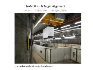
Horn geometry used 18.11. 2009 The advantage of studying this geometry is that the prototype is available at CERN and experimental verification is possible. Present Superbeam horn dimensions are comparable to the NF ones.
Prototype available at CERN 18.11. 2009
1 ELEMENTS MAT NUM Y Z X 1 ELEMENTS MAT NUM Superbeam horn FE model Superbeam horn FE model Finite-element model of the horn 18.11. 2009
Approximate modelling of magnetic forces 18.11. 2009 The analsis assumes cylindrical geometry Inner cylinder with radia RI, RII and thickness t=RII-RI Outer cylinder with radia R’I, R’II and the same thickness Magnetic field distribution:
Approximate modelling of magnetic forces 18.11. 2009 Lorentz force: Definition of the pressure: Assuming uniform current density over thickness: In the case of thin cylindrical shells:
Horn response to magnetic field – FE harmonic analysis 18.11. 2009 Response at a selected point to a harmonic current with amplitude 300 kA
Horn response to a single current pulse 18.11. 2009 Response at a selected point to a current pulse of amplitude 300 kA of 100 s duration
Comments on the response under pulse excitation 18.11. 2009 Displacement and stress in the beam middle-point excited by a half-sine pulse applied at the middle point, pulse duration/period of the lowest mode = 3 The corresponding plots when pulse duration/period over lowest mode = 0.01
Comments on response under pulse excitation 18.11. 2009 Impulse resonance The case with no damping The effect of damping
Coupled magneto-structural analysis – static benchmark solution 18.11. 2009 Infinite solenoid with a circumferential current density (per area): Analytical solution: Magnetic field vector inside the cylinder: Lorentz force: Mechanical equations of equilibrium:
Coupled magneto-structural analysis – static benchmark solution 18.11. 2009 Constitutive equations: Mechanical boundary conditions:
Coupled magneto-structural analysis – static benchmark solution 18.11. 2009 Stresses in the solenoid (F.C. Moon „Magneto-solid Mechanics”, 1984): where:
FEM vs. Analytical solution 18.11. 2009 Material properties: E=10.76*1011 N/m2, =0.35, =0 Geometric properties: a=0.01 m, b=0.02 m Loading: J=106 A/m2 Results for r=0.017 m Analytical Ansys Bz = 0.003770 T Bz= 003750 T t =62.44 N/m2 t =61.34 N/m2
Thermomechanical analysis under Jule heating 18.11. 2009 Parameters used: Max. current: 300 kA Pulse repetition rate : 50 Hz Pulse length: 100 s Jule losses calculated for the NF horn at CERN by J.M. Maugain, S.Rangod, F. Voelker: 18 or 40 kW. These have been applied as uniform heat sources over the part of horn carrying the current Water flow: 82 l/min Water inlet temperature: 25 oC Water outlet temperature: 40 oC
1 NODAL SOLUTION STEP=1 SUB =1 TIME=1 TEMP (AVG) RSYS=0 SMN =25 SMX =79.838 Y Z X MN 1 NODAL SOLUTION MX STEP=1 SUB =1 TIME=1 TEMP (AVG) RSYS=0 SMN =25 SMX =131.287 25 37.186 49.372 61.559 73.745 31.093 43.279 55.466 67.652 79.838 Current dissipation 18kW Y Z X MN MX 25 48.619 72.239 95.858 119.478 36.81 60.429 84.049 107.668 131.287 Current dissipation 40kW Temperature distribution 18.11. 2009
1 NODAL SOLUTION STEP=1 SUB =1 TIME=1 SEQV (AVG) DMX =.001183 SMN =22610 SMX =.282E+09 Y Z X MN 1 NODAL SOLUTION MX STEP=1 SUB =1 TIME=1 SEQV (AVG) DMX =.001215 22610 .628E+08 .125E+09 .188E+09 .251E+09 SMN =6627 .314E+08 .941E+08 .157E+09 .220E+09 .282E+09 SMX =.288E+09 New HORN 03/2009, thermal static analysis Y Z MN X MX 6627 .639E+08 .128E+09 .192E+09 .256E+09 .320E+08 .959E+08 .160E+09 .224E+09 .288E+09 Current dissipation 40kW Thermal stresses 18.11. 2009 Stresses of the order of 95 MPa for the more intensive of the two heat sources. Locally high stresses due to numerical singularities.
Integration of the target inside the horn 18.11. 2009 Concept of integration of a pebble-bed target inside a horm (P. Sievers) For a 4 MW beam power dissipated in the target amounts to: 600 kW (estimated by P. Sievers) 200 kW (from the report by A.Longhin)
1 NODAL SOLUTION STEP=1 SUB =1 TIME=1 TEMP (AVG) RSYS=0 SMN =25 SMX =131.287 Y Z X MN MX 1 NODAL SOLUTION STEP=1 SUB =1 25 48.619 72.239 95.858 119.478 TIME=1 36.81 60.429 84.049 107.668 131.287 TEMP (AVG) +200kW RSYS=0 SMN =24.964 SMX =131.287 Y Z X MN MX 24.964 48.591 72.219 95.846 119.474 36.777 60.405 84.032 107.66 131.287 +600kW Horn temperature distribution under Jule heating and radiation from the target 18.11. 2009 Conservative assumption that all power dissipated in the target goes to the horn. Additional heating causes a local temperature increase of 30 to 50 deg. These are preliminary results, assuming that the temperature of the cooling water is not influenced by the additional heat source (higher water flow). A FLOTRAN analysis has just started.
Plans for the near future 18.11. 2009 Continuation of the dynamic analysis of the horn under a sequence of pulses (calculation of stresses, coupled-field dynamic analysis) Transient thermomechanical analysis More detailed analysis of the thermomechanical phenomena accounting for the water flow using FLOTRAN Horn fatigue life estimate, based on the combined calculated dynamic and thermomechanical stress levels.(The present CERN estimate is only 6 weeks!) Modelling of the present superbeam geometry