Download
1 / 59
720 likes | 1.1k Vues
Heat Power Engineering. Chapter No: 3 Air Compressors. Air compressor. Pneumatics: A system which uses compressed air is called pneumatics. It deals with the study of behaviour & application of compressed air

E N D
Heat Power Engineering • Chapter No: 3 Air Compressors
Air compressor • Pneumatics: A system which uses compressed air is called pneumatics. • It deals with the study of behaviour & application of compressed air • A basic pneumatic system consist of a source of compressed air, control valves, pipelines & pipe fittings and pneumatic accessories like filter, regulator and lubricator
Application of compressed air • For operating pneumatic tools such as drills, screw drivers, hammers, chiessels • For pneumatic cranes • For pneumatic brakes of automobiles, railways and presses • For agricultural accessories such as dusters and sprayers
Application of compressed air • For drive of CNC machine tools • For pneumatic conveying of materials • For pneumatic gauging, inspection and low cost automation systems
Introduction to compressors • An air compressor is a mechanical device that increases the pressure of air by reducing volume. • Air is compressible, the compressor reduces the volume of air and induces pressure in the air • An air compressor converts electrical energy into kinetic energy in the form of the air
Introduction to compressors • The compressed air is stored in the air receiver and can be used for cleaning under pressure, generating torque and develop force using actuators • This source is free of cost, safe, flexible and convenient • Air compressor has very few parts hence maintenance is very low
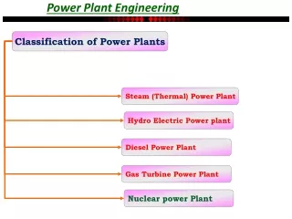
Classification of air compressor • Air compressors are classified according to method of energy transfer and pressure generation i.e. positive displacement and dynamic compressors • Positive displacement compressors work on the principle of increasing the pressure of air by reducing the volume of air in an enclosed chamber
Classification of air compressor • Dynamic compressors works on the principle of imparting the energy by rotating vanes of impeller on air flowing through casing that increases pressure in air
Classification of air compressor • According to number of stages Single stage, double stage, three stage of multiple stage • According to action Single acting or double acting • According to position of cylinder w.r.t. crankshaft Cylinders inline, vertical, radial position, V-type cylinder arrangement
Classification of air compressor • According to prime mover Electric motor drive or IC engine drive, Gas turbine drives • According to cooling medium Air cooled, water cooled air compressors
Reciprocating Air compressors • Reciprocating air compressors are positive displacement type of air compressors. • These are piston & diaphragm type, vane type, gear type, screw type compressors.
Reciprocating Air compressors • The principle of operation is same but according to stages the delivery pressure is different in each compressor.
Reciprocating Air compressors • A reciprocating air compressor consist of a piston which is enclosed within a cylinder and equipped with suction and discharge valve • The piston receives power from electric motor or IC engine.
Reciprocating Air compressors • The compression of air is done by first drawing a volume of air into the cylinder through suction valve during suction stroke of piston and then compressed and discharged through delivery valve during delivery stroke
Single stage Reciprocating Air compressors • In this type the entire compression is carried out in a single cylinder
Single stage Reciprocating Air compressors • When piston starts moving downwards, the pressure inside the cylinder falls below atmospheric pressure that opens suction valve. • The pressure of the air in the cylinder rises during compression and at the end of compression, delivery valve opens and discharges the compressed air into the receiver tank.
Single stage Reciprocating Air compressors • Single stage air compressor develop pressure upto 7 bar. • For higher pressures multistage compressors are suitable
Double stage Reciprocating Air compressors • It consist of two cylinders – low pressure cylinder and high pressure cylinder • Piston, crankcase, piston rod, crank, crankshaft, oil, fins etc.
Double stage Reciprocating Air compressors • The fresh air is drawn inside the L.P. cylinder through inlet suction filter. • This air is compressed by piston • As the piston moves towards the end of cylinder, the air compression took place.
Double stage Reciprocating Air compressors • The delivery valve opens and this compressed air from L.P. cylinder is directed to enter inside the high pressure cylinder. • In high pressure cylinder this pressurised air is further compressed to higher pressure.
Double stage Reciprocating Air compressors • The high pressure air from H.P. cylinder is then delivered to receiver through discharge valves. • In this compressor, a pressure of air delivered is upto 13 bar.
Advantages • Simple in design • Lower initial cost • Easy to install • Higher effeiciency
Disadvantages • Number of moving parts are more • Higher maintenance cost • Heavy foundation is required as it has vibration problem • Cannot run at full capacity
Rotary vane compressor • It is positive displacement type compressor. • It provides higher efficiency and flow rates over a wide range of pressure • Rotary vane compressor consist of rotor with a number of vanes inserted in the radial slots cut in rotor.
Rotary vane compressor • The rotor is mounted eccentric in a casing. • The vanes slides radially in and out of the rotor. • As the rotor rotates at higher speed, centrifugal force throws the vanes outward keeping the end of vane in contact with the stator ring.
Rotary vane compressor • As the rotor turns, compression is achieved as the volume goes from a maximum at intake port to minimum at the exhaust port. • An oil is injected into the air intake and along the stator walls to cool the air and lubricate bearing and vanes and to provide a seal between the vane and stator wall to reduce internal leakage.
Advantages: • Simple design • Compact in size • Light in weight • Easy to install • Low cost • Low maintenance cost • Longer life • Few moving parts • Low rotational speed • Expensive foundation not required
Disadvantages: • Lower efficiency • Difficulty with higher pressure above 200 psi • Oil injected designs have oil carryover
Centrifugal compressor • It is dynamic compressor. • It consist of a rotating impeller which rotates at higher speed (upto 60000 rpm) • An impeller fitted inside casing force the air to the rim of impeller, increasing velocity of air.
Centrifugal compressor • A diffuser (divergent shape of casing) section converts the velocity of air to cause an increase in pressure. This process is called dynamic compression. • These compressors are used for continuous, stationary services in industries like oil refineries, chemical and petrochemical plants, natural gas processing plants.
Centrifugal compressor • These are also used in IC engine superchargers and turbochargers. • In gas turbine plants • It can provide extremely high output pressures greater than 10000psi.
Screw compressor • It consist of two screws - one with convex and the other with concave contour mostly called male and female rotor respectively. • These two screws gets rotating by means of gear trips there by sucking the air through an inlet port in chamber and then compressing the same
Screw compressor • The helix of the male and female rotor screw is designed to permit complete charging of the inter lobe space before the re-mesh. • On completion of the filling operation the inlet end of male and female lobes begins to re-engage thus reduces the volume of air continuously.
Screw compressor • Thus compression begins and air is discharged at the end of other side. • There is no contact between male and female rotors and casing. Hence no lubrication require but oil may injected for the purpose of cooling.
Twin lobe compressor • It is used in applications where higher flow at comparatively low pressure is required.
Twin lobe compressor • Here two lobes are placed in a casing • The air is transferred from suction side to the delivery side with continuous rotation of two lobes • The lobes are precisely maintained and the casing also maintained to close tolerances • It has limited compression ratio @ 1.7