Introduction to Microwaves: Fundamentals, Properties, and Applications
1.13k likes | 1.71k Vues
Microwaves are a segment of the electromagnetic spectrum with frequencies ranging from 300 MHz to 300 GHz and wavelengths from 100 cm to 1 mm. This short-wave radiation exhibits unique properties, such as being able to reflect off conducting surfaces and the ability to flow through ordinary cables. Microwaves have numerous applications in telecommunications, radar systems, and industrial processes, offering advantages like increased bandwidth and reliability while presenting challenges related to fading effects. Understanding microwaves is crucial for modern technology and telecommunications.

Introduction to Microwaves: Fundamentals, Properties, and Applications
E N D
Presentation Transcript
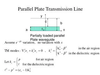
Microwaves Microwaves are electromagnetic waves whose frequencies range from about 300 MHz – 300 GHz (1 MHz = 10 6 Hz and 1 GHz = 10 9 Hz) or wavelengths in air ranging from 100 cm – 1 mm. The word Microwavemeans very short wave, which is the shortest wavelength region of the radio spectrum and a part of the electromagnetic spectrum.
Properties of Microwaves • Microwave is an electromagnetic radiation of short wavelength. • They can reflect by conducting surfaces just like optical waves since they travel in straight line. • Microwave currents flow through a thin outer layer of an ordinary cable. • Microwaves are easily attenuated within short distances. • They are not reflected by ionosphere
Advantages and Limitations 1. Increased bandwidth availability: • Microwaves have large bandwidths compared to the common bands like short waves (SW), ultrahigh frequency (UHF) waves, etc. • For example, the microwaves extending from = 1 cm - = 10 cm (i.e) from 30,000 MHz – 3000 MHz, this region has a bandwidth of 27,000 MHz. 2. Improved directive properties: • The second advantage of microwaves is their ability to use high gain directive antennas, any EM wave can be focused in a specified direction (Just as the focusing of light rays with lenses or reflectors)
Advantages and Limitations 3. Fading effect and reliability: • Fading effect due to the variation in the transmission medium is more effective at low frequency. • Due to the Line of Sight (LOS) propagation and high frequencies, there is less fading effect and hence microwave communication is more reliable. 4. Power requirements: • Transmitter / receiver power requirements are pretty low at microwave frequencies compared to that at short wave band.
Advantages and Limitations 5.Transparency property of microwaves: • Microwave frequency band ranging from 300 MHz – 10 GHz are capable of freely propagating through the atmosphere. • The presence of such a transparent window in a microwave band facilitates the study of microwave radiation from the sun and stars in radio astronomical research of space.
Applications • Microwaves have a wide range of applications in modern technology, which are listed below • Telecommunication: Intercontinental Telephone and TV, space communication (Earth – to – space and space – to – Earth), telemetry communication link for railways etc. • Radars: detect aircraft, track / guide supersonic missiles, observe and track weather patterns, air traffic control (ATC), burglar alarms, garage door openers, police speed detectors etc.
3.Commercial and industrial applications • Microwave oven • Drying machines – textile, food and paper industry for drying clothes, potato chips, printed matters etc. • Food process industry – Precooling / cooking, pasteurization / sterility, hat frozen / refrigerated precooled meats, roasting of food grains / beans. • Rubber industry / plastics / chemical / forest product industries • Mining / public works, breaking rocks, tunnel boring, drying / breaking up concrete, breaking up coal seams, curing of cement. • Drying inks / drying textiles, drying / sterilizing grains, drying / sterilizing pharmaceuticals, leather, tobacco, power transmission. • Biomedical Applications ( diagnostic / therapeutic ) – diathermy for localized superficial heating, deep electromagnetic heating for treatment of cancer, hyperthermia ( local, regional or whole body for cancer therapy).
Other Applications • Identifying objects or personnel by non – contact method. 5. Light generated charge carriers in a microwave semiconductor make it possible to create a whole new world of microwave devices, fast jitter free switches, phase shifters, HF generators, etc.
Microwave Engineer's Work: An Example - Magnetron Development
Magnetron oscillator • Magnetrons provide microwave oscillations of very high frequency. Types of magnetrons • Negative resistance type • Cyclotron frequency type • Cavity type
Description of types of magnetron Negative resistance Magnetrons • Make use of negative resistance between two anode segments but have low efficiency and are useful only at low frequencies (< 500 MHz). Cyclotron frequency Magnetrons • Depend upon synchronization between an alternating component of electric and periodic oscillation of electrons in a direction parallel to this field. • Useful only for frequencies greater than 100 MHz. Cavity Magnetrons • Depend upon the interaction of electrons with a rotating electromagnetic field of constant angular velocity. • Provide oscillations of very high peak power and hence are useful in radar applications
Cavity Magnetrons Fig (i) Major elements in the Magnetron oscillator
Construction • Each cavity in the anode acts as an inductor having only one turn and the slot connecting the cavity and the interaction space acts as a capacitor. • These two form a parallel resonant circuit and its resonant frequency depends on the value of L of the cavity and the C of the slot. • The frequency of the microwaves generated by the magnetron oscillator depends on the frequency of the RF oscillations existing in the resonant cavities.
Description • Magnetron is a cross field device as the electric field between the anode and the cathode is radial whereas the magnetic field produced by a permanent magnet is axial. • A high DC potential can be applied between the cathode and anode which produces the radial electric field. • Depending on the relative strengths of the electric and magnetic fields, the electrons emitted from the cathode and moving towards the anode will traverse through the interaction space as shown in Fig. (iii). • In the absence of magnetic field (B = 0), the electron travel straight from the cathode to the anode due to the radial electric field force acting on it, Fig (iii) a.
Description • If the magnetic field strength is increased slightly, the lateral force bending the path of the electron as given by the path ‘b’ in Fig. (iii). • The radius of the path is given by, If the strength of the magnetic field is made sufficiently high then the electrons can be prevented from reaching the anode as indicated path ‘c’ in Fig. (iii)), • The magnetic field required to return electrons back to the cathode just grazing the surface of the anode is called the critical magnetic field (Bc) or the cut off magnetic field. • If the magnetic field is larger than the critical field (B > Bc), the electron experiences a greater rotational force and may return back to the cathode quite faster.
Fig (iii) Electron trajectories in the presence of crossed electric and magnetic fields(a) no magnetic field(b) small magnetic field(c) Magnetic field = Bc(d) Excessive magnetic field
Working Fig (iv) Possible trajectory of electrons from cathode to anode in an eight cavity magnetron operating in mode
Working • The RF Oscillations of transient nature produced when the HT is switched on, are sufficient to produce the oscillations in the cavities, these oscillations are maintained in the cavities reentrant feedback which results in the production of microwaves. • Reentrant feedback takes place as a result of interaction of the electrons with the electric field of the RF oscillations existing in the cavities. • The cavity oscillations produce electric fields which fringe out into the interaction space from the slots in the anode structure, as shown in Fig (iv). • Energy is transferred from the radial dc field to the RF field by the interaction of the electrons with the fringing RF field.
Working • Due to the oscillations in the cavities, the either sides of the slots (which acts as a capacitor) becomes alternatively positive and negative and hence the directions of the electric field across the slot also reverse its sign alternatively. • At any instant the anode close to the spiraling electron goes positive, the electrons gets retarded and this is because; the electron has to move in the RF field, existing close to the slot, from positive side to the negative side of the slot. • In this process, the electron loses energy and transfer an equal amount of energy to the RF field which retard the spiraling electron. • On return to the previous orbit the electron may reach the adjacent section or a section farther away and transfer energy to the RF field if that part of the anode goes positive at that instant.
Working • This electron travels in a longest path from cathode to the anode as indicated by ‘a’ in Fig (iv), transferring the energy to the RF field are called as favoured electrons and are responsible for bunching effect and give up most of its energy before it finally terminates on the anode surface. • An electron ‘b’ is accelerated by the RF field and instead of imparting energy to the oscillations, takes energy from oscillations resulting in increased velocity, such electrons are called unfavoured electrons which do not participate in the bunching process and cause back heating. • Every time an electron approaches the anode “in phase” with the RF signal, it completes a cycle. This corresponds to a phase shift 2. • For a dominant mode, the adjacent poles have a phase difference of radians, this called the - mode.
Working • At any particular instant, one set of alternate poles goes positive and the remaining set of alternate poles goes negative due to the RF oscillations in the cavities. • AS the electron approaches the anode, one set of alternate poles accelerates the electrons and turns back the electrons quickly to the cathode and the other set alternate poles retard the electrons, thereby transferring the energy from electrons to the RF signal. • This process results in the bunching of electrons, the mechanism by which electron bunches are formed and by which electrons are kept in synchronism with the RF field is called phase focussing effect. electrons with the fringing RF field.
Working • The number of bunches depends on the number of cavities in the magnetron and the mode of oscillations, in an eight cavity magnetron oscillating with - mode, the electrons are bunched in four groups as shown in Fig (v). • Two identical resonant cavities will resonate at two frequencies when they are coupled together; this is due to the effect of mutual coupling. • Commonly separating the pi mode from adjacent modes is by a method called strapping. The straps consist of either circular or rectangular cross section connected to alternate segments of the anode block.
Performance Characteristics • Power output: In excess of 250 kW ( Pulsed Mode), 10 mW (UHF band), 2 mW (X band), 8 kW (at 95 GHz) • Frequency: 500 MHz – 12 GHz • Duty cycle: 0.1 % • Efficiency: 40 % - 70 %
Applications of Magnetron • Pulsed radar is the single most important application with large pulse powers. • Voltage tunable magnetrons are used in sweep oscillators in telemetry and in missile applications. • Fixed frequency, CW magnetrons are used for industrial heating and microwave ovens.
Why RF ? • Ever-Growing Wireless Applications • Personal Communication Systems • Satellite Systems • Global Positioning Systems • Wireless Local-Area Networks • Strong Demand for Wireless Engineers • Digital is HOT • Analog is COOL • RF Design is an ART
Course Objectives • Circuit Concepts for RF Systems • Transmission Lines, Impedance Matching • Noise and Distortion Analysis • Filter Design • RF System Components • Low-Noise Amplifiers, Power Amplifiers • Mixers and Oscillators • Elementary Transmitter/Receiver Architectures and Their Board-Level Implementation
Emphasis ??? • Designing RF Integrated Circuits • Some Engineers • Designing With RF Integrated Circuits • More Engineers • Difficult to Satisfy Both Objectives
Textbooks • The Design of CMOS Radio-Frequency Integrated Circuits • Thomas H. Lee (required) • Planar Microwave Engineering: A Practical Guide to Theory Measurements and Circuits • Thomas H. Lee • Radio Frequency Circuit Design • W. Alan Davis and Krishna K. Agarwal • Advanced RF Engineering for Wireless Systems and Networks • Arshad Hussain • Microwave and RF Design of Wireless Systems • David M. Pozar • High-Frequency Techniques • Joseph F. White
Some Good Advice … • Read the Syllabus • Come to Class (Come to Class Early) • Do the Homework (But Not One Hour Before a Deadline) (And Don’t Give Up Easily) • Enjoy the Course !
Basic Radio Systems Data In Power Amplifier Bandpass Filter Modulator IF Filter Mixer X Transmitter Local Oscillator IF Amplifier Bandpass Filter Low-Noise Amplifier Demodulator IF Filter Mixer X Receiver Local Oscillator Data Out
Connecting the Boxes • Antenna RF Link Between Transmitter and Receiver (Marginal Issue for EE 448) • Transmission-Line Connections Between Internal Transmitter/Receiver Components • l = Velocity / Frequency • Circuit Dimensions Comparable to l at High Frequencies (>> 1 GHz) • “Distributed” Circuit Behavior
Real Computer Issues data Dev a Dev b Signal Measured here Clk Switch Threshold Measured clock is non-monotonic and because of this the flip flop internally may double clock the data.
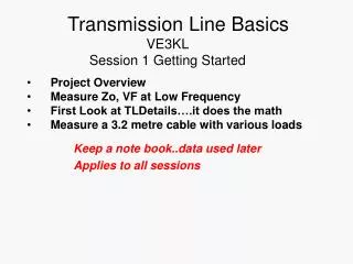
Agenda • The Transmission Line Concept • Transmission line equivalent circuits and relevant equations • Reflection diagram & equation • Loading • Termination methods and comparison • Propagation delay • Simple return path ( circuit theory, network theory come later)
Two Transmission Line Viewpoints • Steady state ( most historical view) • Frequency domain • Transient • Time domain • Not circuit element Why?
Transmission Line Concept Power Frequency (f) is @ 60 Hz Wavelength (l) is 5 106 m ( Over 3,100 Miles) Power Plant Transmission Line Could be considered as Non-Transmission Line Consumer Home
Integrated Circuit Stripline T Microstrip PCB substrate Cross section view taken here W Via FR4 Dielectric Cross Section of Above PCB Copper Trace Signal (microstrip) Ground/Power Signal (stripline) T Copper Plane Signal (stripline) Ground/Power Signal (microstrip) W PC Transmission Lines Signal Frequency (f) is approaching 10 GHz Wavelength (l) is 1.5 cm ( 0.6 inches) Stripline Micro-Strip
Key point about transmission line operation Voltage and current on a transmission line is a function of both time and position.
Examples of Transmission Line Structures- I • Cables and wires (a) Coax cable (b) Wire over ground (c) Tri-lead wire (d) Twisted pair (two-wire line) • Long distance interconnects
Segment 2: Transmission line equivalent circuits and relevant equations • Physics of transmission line structures • Basic transmission line equivalent circuit • Equations for transmission line propagation