Download
1 / 21
210 likes | 292 Vues
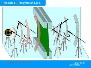
This review covers specifications, layout, testing, calculations, design, and service considerations of the power supply system transmission line. It includes details on materials, construction, cooling, vibration, support structures, and serviceability.

E N D
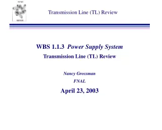
Transmission Line (TL) Review WBS 1.1.3 Power Supply System Transmission Line (TL) Review Nancy Grossman FNAL April 23, 2003
Outline • Overview & Specifications (N. Grossman, 10’) • Scope of review • General Layout & Overall Specifications • Schedule, Concerns • Response to Recommendations (2/26/02 review) (N. Grossman, 10’) • Testing at MI8 (J. Hylen, 15’) • Remote clamp & joint testing so far • Future plans • Ionization Calculations (J. Hylen, 10’) • Cooling Calculations (A. Stefanik, 10’) • TL through Block & Beyond Design/Status (B. Boettinger, 45’) • Design (clamps, connection, supports) • Heating/cooling (expansion) & Vibration Issues • Service Considerations
Scope and Conceptual Layout:Target Hall Transmission • Material: Aluminum, Dimensions: 12 inches wide by 3/8 inch thick • Width: Stripline nominal width is 12 inches, reduce to 8” from below clamp to horns. • Gap: Stripline nominal spacing between bars is 3/8 inch, can increase in flex region. REMOVABLE28’ SECTION REMOVABLEZ-BAR ROCK WALL BETWEEN PS ROOM AND TARGET HALL- 23’ REMOTE CLAMP HORN 1 JOINT REMOVABLE Z-BAR REMOTE CLAMP HORN 2 JOINT
Scope/Charge to Group • Scope Includes: • Transmission Line design from joint/remote clamp to connection at capacitor bank • Electrical Isolation Considerations • Heating/cooling (thermal expansion) • Vibration • Stands & support structures to hold transmission line in place • Wedge clamps in the transmission line block • Support stands in the target hall • Three point support structure in 24” round penetration from hall to PS room • Service Considerations • Removing the section through the wall • Horn replacement • Cover to protect transmission line – to be designed, simple slanted sheet metal • Charge: • Look at overall design. • Consider QA, longevity, ESH issues. • Comment back to grossman@fnal.gov within a week.
MI-8 Fingers, Remote Clamp Remote clamp plugged in @ MI-8 Horn 1 joint/electrical plug @ MI-8 Routine pulsing of prototype horn 1, production horn 1 joint, remote clamp underway: ~370,000 pulses to date. Goal is 1 million pulses, 1/2 offset/flexed
Joints and Remote Clamp Horn 1 joint, remote clamp at MI-8 Horn 2 joint in machine shop (now done)
Overall Specifications/Concerns 1. Lifetime: • Part of stripline connected to horn will be replaced each time a horn is replaced, ~>1 year. • Part of stripline within stripline block (includes clamp) does not have to be replaced every time a horn is replaced, but we will most likely have a spare just in case. • Lifetime of NuMI ~ 10 years 2. Radiation Environment such that ceramics must be used near the beam, but not necessary above the module/T-blocks. • Ceramics spacers from horn to top of module/block • G-10 spacers used beyond that as insulators 3. Vibration, keep to a minimum everywhere. • Biggest horn vibration is from stripline (MI8 measurements) • Not near horn natural frequencies (200 Hz), damping times short wrt rep-rate • Clamp every 12” in target hall • Pulsed for about 9.5 millions pulses at MI-8 (non-joint portion of transmission line) with no problems – clamping every 12” • More on recent vibration measurements from Jim.
Overall Specifications/Concerns 4. Cooling • Target chase cooled by ~24,000 cfm flowing in the beam direction in the horn region and back in the opposite direction between the top of the T-blocks and the concrete cap. • Beam heating: ~183 KW/m3 (transmission line near the beam) • TL Electrical heating: ~27 KW/m3 (flex joint number) • Assume air cooling from target chase is sufficient (A. Stefanik talk) • Want air flow through TL shield block from top of module to horn (this air flow cools stripline) • Air dam is needed at the H-block cover between the module and the stripline along the target hall wall (intended to contain air-borne radiation). 5. Service Considerations: • Must not block survey holes in T-blocks just off module ends, need direct vertical line of sight. • Two removable sections to allow removal of section through the wall (28’). • Removable “z-bar”s at top of module/block. Allows replacement of horns.
Transmission Line: Through the Block ( figure slightly out of date )
Response to Recommendations:Horn PS/TL Review (August 2001) • Consider using a dynamic type fastener (e.g., spiralock nut) in the clamp joints and stripline support brackets. • This is being done, except in the block region where it is tack-welded to the fasteners. • Consider measuring bolt preload in critical connections by measuring bolt stretch as opposed to bolt torque. • Not sure how to implement this – ideas? • Consider longitudinal damping along the TL section along the Target Hall wall to damp out possible undamped vibrations from electrical pulsing. • Using polyeruthane isolators and swinging end-links (see Bill’s talk). • Worry about scratching the silver-plating off the TL “fingers” when clamping/unclamping. • Have seen no damage in the silver-plating on the TL fingers out at MI-8 and they have been connected and disconnected a few times. (more from Jim)
Response to Recommendations:TL, Remote Clamp, TL Block Review (Feb. 2002) • Flex Joint Comments (joint with slits) • No longer using a joint with slits. ANSYS shows we can get sufficient flexibility with the non-slitted design. Single strip force tests agree with the ANSYS analysis. Testing at MI-8 of the horn1 joint is going well. More from Jim – not specifically part of this review. • Suggest quantitative measurements be made at MI-8 (deflection at specific points, resonant frequencies, etc.) to compare to ANSYS calculations (and any other calculations) and thus support longevity estimates. • We are making some quantitative measurements at MI-8 and will compare measurements with predictions– Jim will talk about this. • Concerns abut a tight testing schedule at MI-8 which might be hard to meet if problems are encountered. • Agree. We have encountered problems, testing is tight, and we hope to make it (more from Jim). Can delay installation of horn PS & continue testing longer. • Concerns with human resources – lack of. • This is a constant battle we continue to fight. • Suggest pre-assemble entire setup (power supply to horns) at MI-8. • We will do this to the extent that we can.
Schedule & Concerns Schedule: • MI-8 testing until Horn PS removed for installation. • Test pulsing of horn 1 and horn 2 on test stand.
Schedule & Concerns Specific Concerns: • Making sure all bolts on the TL clamps are tighten (and remain tightened) • Checkout checklist item • Periodic checks in Target Hall? • QA that clamps are put together correctly • If doesn’t look like it is going together well, stop and ask expert. • Alignment rods at removable sections General Concerns: • Resources (manpower) • Engineering/drafting to get the design done and parts ordered/made • Technicians to get it assembled and installed • Fitting it all in with the target hall shield block installation & Module installation • Concerns about damaging the TL parts • Final connections of the TL to the horns/PS are near the critical path The transmission line (and joint) have always been underestimated in their complexity (cost, time to make, problems encountered in installation/testing).