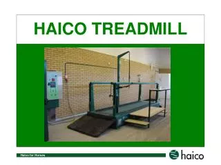
Reebok ICE Treadmill
Reebok ICE Treadmill. Service Manual. Specifications. Length: 1600mm Width: 770mm Running Area: 400X1200mm Weight of product: 51kgs Shipping Weight: 61kgs Speed Range: 0.5~8.4 mph (0.8~14 kph) in 0.1mph or 0.1kph increments Incline Range: Manual / 2 levels TFT TV Kit: No

Reebok ICE Treadmill
E N D
Presentation Transcript
Reebok ICE Treadmill Service Manual
Specifications Length: 1600mm Width: 770mm Running Area: 400X1200mm Weight of product: 51kgs Shipping Weight: 61kgs Speed Range: 0.5~8.4 mph (0.8~14 kph) in 0.1mph or 0.1kph increments Incline Range: Manual / 2 levels TFT TV Kit: No Fold Up: Yes Power Fold Up: No Manual Adjustment Shock: No Intelligent Suspension System: No Swing Arm Suspension: No Motion control: No Hand Pulse Sensor: Yes Wireless Pulse Sensor: No Programs: Quick Start, Target time, Target distance, Target calories, 15/30/45 MINUTES PRESET Power Requirement: 240vac ± 10% 50/60Hz 8Amps Motor: DC motor (Model: GMD82-04-1B180VDC) Emergency Stop: Pull the emergency stop key 770mm 1600mm Page 1
Parts Explosive Drawing Page 2
Tools require for service procedure • Digitize display multi meter • 17mm wrench 2pcs • 13mm wrench • 10mm wrench • Phillip screw driver • 5mm Allen wrench • 6mm Allen wrench • 8mm Allen wrench • 5mm Allen wrench with T hand bar • 6mm Allen wrench with T hand bar • Long nose plier Page 13
Remove The Motor Cover Step 1: Use Phillip screw driver to open on lower motor cover 4 bolts Step 2: Move down the front transport wheel frame, then both front foots will going up. Step 3: Use Phillip screw driver to open on both front motor cover 8 bolts and lower motor cover front 2 bolts. Step 4: Use Phillip screw driver to open on both motor cover near both side rail 2 bolt. Step 5: Use Phillip screw driver to open on both side rail end cover 2 bolts. Step 6 : Move both side rail to leave motor cover edge. Page 14
Step 7 : Remove the motor cover. Page 15
Remove the driver motor Step 1: Follow Remove The Motor Cover instruction to open motor cover. Step 2: use Phillip screw driver to open fix front motor cover-right 4 bolts. Step 3: Move front motor cover-right like figure instruction. Step 4: Use 13mm wrench to open bracket tension nut and remove spacer and PU spacer or tension spring. Then remove the motor belt from motor fly wheel. Step 5: Prepare a L shape 17mm socket wrench and a 17mm wrench. Step 6: Then use L shape 17mm socket wrench and 17mm wrench to open motor bracket longer bolt and nut. Step 7: Remove drive motor set from treadmill. Page 16
Step 7 : Use a 5mm Allen wrench to open fix motor bracket 2 bolts then remove the drive motor from motor bracket. Page 17
Remove Front and Rear roller Step 1: Follow Remove the motor cover instruction to open motor cover. Step 3: Use a 5mm Allen wrench to open fix rear roller 2 bolt. Step 2: Use Phillip screw driver to open on both side rail end cover 2 bolts. Step 4: Remove the rear roller. Step 5: Use a 5mm Allen wrench to open front roller bolt at left frame. Step 6: Remove front roller and drive belt. Page 18
Remove run desk and run belt Step 1: Follow Remove the motor cover instruction to open motor cover. Step 2: Follow Remove front and rear roller instruction to open motor cover. Step 3: Use a Phillips screw driver to open fix run desk 8 bolts. Step 4: Remove run desk and run belt from main frame together. Step 4: Remove run belt from run desk. Page 19
Install and adjust motor control board When install a new motor control board must adjust SPEED and AMP both VR at main control board. Confirm the new control board voltage 220VAC correct. (see Fig.1 with white color level). Before install a new main control board on unit frame, first adjust SPEED and AMP both VR (see Fig.2), all turn to clockwise at minimum. After complete install a new main control board include plugged all connector at main control board then switch power on treadmill and insert safety Key, and press START button set console speed at 0.8kph(0.5mph). Use a VR adjuster turn SPEED VR to counter clockwise and use a RPM or SPEED meter to measure actual speed on running belt moving at same time, still running belt speed at 0.8kph(0.5mph). After finished adjust SPEED VR then adjust AMP VR, it’s for adjust torque while unit at lower speed. When running belt moving at 0.8kph(0.5mph), first step two hands hold and firm at front handle bar or both side rail handle bar then move feet on running belt and a little bit to resist Running belt, if running belt stop then adjust AMP VR to counter clockwise a little bit, after adjust AMP VR then use feet test again, repeat this test action couple tomes, still running belt not stop from feet little force. If adjust AMP VR too much higher, when user workout at treadmill running belt will suddenly speed up at short time during every pace. Do not adjust AMP VR too much higher because it’s will to bring DC driver short life. SPEED AMP Fig.1 Fig.2 Page 20
Circuit Diagram Page 21
230 VAC AT OUTLET NO RESET CHECK HOME CIRCUIT BREAKER NO IS SAFETY KEY INSERT ? YES IS POWER SWITCH ON ? IS AC LIGHT ON SWITCH ? NO YES NO YES RESET YES CHECK 8PIN CONNECTION AT RELAY BOARD IS THE CIRCUIT BREAKER TRIPPED ? INSERT SAFETY KEY NO DISPLAY REPAIR YES BAD RECONNECT GOOD REPLACE CIRCUIT BREAKER NO CHECK 6PIN CONNECTOR OF RELAY BOARD TO CONTROL BOARD CHECK VOLTAGE ACROSS CIRCUIT BREAKER BAD RECONNECT 230 VAC GOOD REPLACE SWITCH CHECK WIRE CONNECTION 0 VAC CHECK VOLTAGE L1 L2 AT CONTROL BOARD 0 VAC CHECK VOLTAGE ACROSS SWITCH 230 VAC 230 VAC CHECK VOLTAGE FROM PIN 17V 10V TEST PIN 10V AT CONTROL BOARD 0 VAC 0 VAC REPLACE TRANSFORMER CHECK VOLTAGE AT POWER CORD 10 TO 12 VAC CHECK 6PIN CABLE BAD REPLACE 6PIN CABLE OR RECONNECT 0 VAC REPLACE POWER CORD GOOD CHECK 8PIN CONNECTOR AT COMPUTER BAD RECONNECT GOOD REPLACE COMPUTER Page 22
IS COMPUTER SPEED DISPLAY 0.5mph(0.8kph) WHEN PRESS START BUTTON ? NO CHECK COMPUTER BUTTON PC BOARD OR REPLACE COMPUTER YES GOOD CHECK DC VOLTAGE FROM 6PIN OF ACROSS PIN5 AND PIN4 AT CONTROL BOARD LOOK FOR INCREASE AS FAST BUTTON IS PRESSED CHECK 8PIN CABLE FROM COMPUTER IN LEFT SIDE UPRIGHT TUBE AND CONNECTOR NO NO BELT MOVEMENT REPAIR BAD INCREASE SPEED 0.8 TO 6.2 VDC OUTPUT REPLACE 8PIN CABLE OR RECONNECT CHECK DC VOLTAGE ACROSS M+ M- AT CONTROL BOARD LOOK FOR INCREASE AS FAST BUTTON IS PRESSED 0 VDC REPLACE CONTROL BOARD INCREASE SPEED 0 TO 180 VDC CHECK MOTOR BRUSH CONDITION CHECK DRIVE MOTOR AS PER PROCEDURE BAD REPLACE MOTOR BRUSHES GOOD IS MOTOR TURNING ? NO REPLACE MOTOR Page 23
HAND PLUSE NOT FUNCTIONING RECONNECT YES HEART RATE(HR) NOT FUNCTIONING/ERRATIC READING CHECK HAND PLUSE CONNECTOR IN HAND ARM BOTH SIDE BAD GOOD CHECK CABLE AND RECONNECT CHECK ALL CABLE FROM HAND PLUSE SENSOR TO COMPUTER OL OHMS 0 OHM REPLACE COMPUTER Page 24