
Enhanced Fast Orbit Feedback and Top-off Preparation Techniques at the ALS Facility
E N D
Presentation Transcript
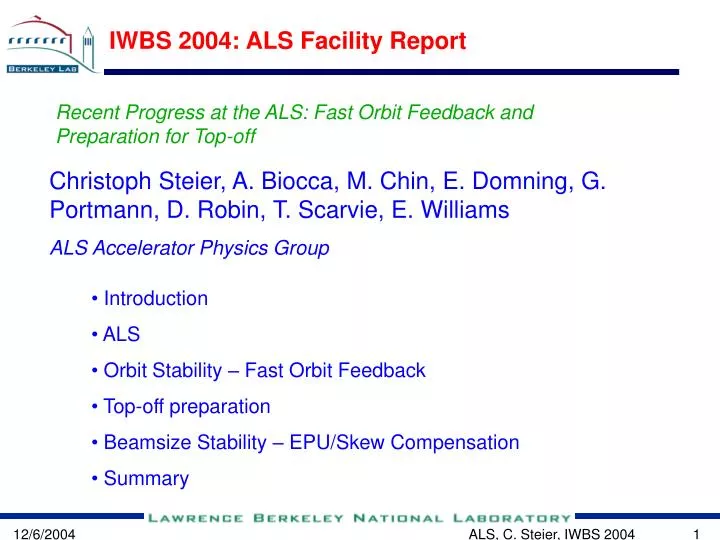
IWBS 2004: ALS Facility Report Recent Progress at the ALS: Fast Orbit Feedback and Preparation for Top-off Christoph Steier, A. Biocca, M. Chin, E. Domning, G. Portmann, D. Robin, T. Scarvie, E. Williams ALS Accelerator Physics Group • Introduction • ALS • Orbit Stability – Fast Orbit Feedback • Top-off preparation • Beamsize Stability – EPU/Skew Compensation • Summary ALS, C. Steier, IWBS 2004
Aerial view of Advanced Light Source ALS, C. Steier, IWBS 2004
ALS Parameters and Beamlines 1/10 Electron Beam Size ALS, C. Steier, IWBS 2004
BPM, Corrector locations • 12 nearly identical arcs – TBA; aluminum vacuum chamber • 96+52 beam position monitors in each plane (original+Bergoz) • 8 horizontal, 6 vertical corrector magnets per arc (94/70 total+chicanes) • Beam based alignment capability in all quadrupoles • 22 corrector magnets in each plane on thinner vacuum chamber pieces - FOFB ALS, C. Steier, IWBS 2004
Orbit Correction • Fast (200 Hz) or slow (10 Hz) local feed forward for all insertion devices (2-d tables for EPUs) • Fast global orbit feedback (1111 Hz, up to 60 Hz closed loop bandwidth) • Slow global orbit feedback (1 Hz) • No frequency deadband between feedbacks • Complete (more correctors) global orbit correction plus local orbit correction at all IDs every 8h after refill. • Photon beam position monitors at ALS are not used to correct beam orbit – instead they feed back on beamline optics. Bandwidth from h to about 10 kHz (IR beamline) ALS, C. Steier, IWBS 2004
Fast Feedback Layout • Motivation: Orbit stability at ALS with passive measures is already very good (1-4 microns rms). Improvement into <mm range requires active/fast feedback • Design choices: • Distances at ALS are relatively large -> distributed system • Wanted to avoid expensive specialized hardware (like reflective memory, DSPs) • Multiplexed (Bergoz) BPMs provide enough bandwidth and low enough noise • D/A converter resolution for corrector magnets was upgraded from 16 to 20 Bit. • Update rate of system is currently 1.11kHz. ALS, C. Steier, IWBS 2004
Computer Hardware of ALS FOFB • Use network timing (network is 100 Mbit/s, full duplex, switched), normal PowerMAC/cPCI hardware used in control system upgrade ALS, C. Steier, IWBS 2004
Feedback Implementation Details • Combination of fast and slow global orbit feedbacks in both planes – no frequency deadband • Fast Feedback currently 24 BPMs in each plane and 22 correctors in each plane. 1.11 kHz update rate, bandwidth DC-60 Hz. Only ½ of singular values used. • Slow Feedback 52 BPMs in each plane, 26 horizontal correctors, 50 vertical correctors, RF frequency correction. 1 Hz update rate, about 60% single step gain, bandwidth DC-0.1 Hz. Typically all SVs used. • Slow feedback communicates with fast feedback to avoid interference in frequency overlap range. Setpoints/golden orbit used by fast feedback is updated at rate of slow feedback. ALS, C. Steier, IWBS 2004
Orbit feedback performance • Fast feedback routinely used in user operation since spring’04 with very positive user response. • Extremely reliable. One beam dump and total of 4 (minute long) feedback outages. • With slow and fast orbit feedback the ALS achieves submicron stability in the vertical plane: • Integrated rms motion 0.01 to 500 Hz in the vertical plane is significantly below 1 micron (at 3.65 m beta function, 23 micron vertical beamsize) • Horizontally the integrated rms motion is now reduced from about 4 to about 2 microns (at 13.5 m beta function and 300 micron horizontal beamsize). • Long term stability (week) is of the order of 3 microns. ALS, C. Steier, IWBS 2004
Beam spectra with feedback • Beam motion with feedback in open (red) and closed loop (blue) at out of loop BPM. • Feedback is quite effective up to about 40 Hz. Right now closed loop bandwidth is about 60 Hz. • Correction at low frequencies down to the BPM noise floor. • System is set up conservatively at the moment – no excitation at higher frequencies. ALS, C. Steier, IWBS 2004
Simulink model of FOFB system • Comparison of simulated (Simulink) and measured step response of feedback system in closed loop • PID parameters were intentionally set to create some overshoot (demonstrating that time constants and performance of system are well understood). ALS, C. Steier, IWBS 2004
Frequency Overlap – Master/Slave • ALS needs slow and fast feedback (do not have enough fast correctors) • Avoided frequency dead band – fast system not DC blocked • Synchronization by SOFB updating FOFB golden orbit ALS, C. Steier, IWBS 2004
‘Long term’ orbit stability Main reasons for long term orbit drift at ALS: • Physical movement of BPM chambers (measured this offline so far) • Current and fill pattern dependence of BPMs (relatively small above 200 mA – less relevant in top-off) • Use of less corrector magnets than BPMs, and a relatively limited number of BPMs (52) and correctors • Rms orbit error over the course of 1.5 days. • first fill is after a beam dump, i.e. the thermal stability is not as good • Normally rms change is below 1 micron ALS, C. Steier, IWBS 2004
Outlook • Will continue to improve orbit feedback • Fast feedback is not completely optimized, yet. • Upgrade networking to Gbit. • Faster CPUs, better ADCs/DACs. • Further optimize digital filter parameters. • Implement narrowband 60 Hz digital notch filter. • Incorporate more stable Bergoz BPMs • Currently 52 installed, goal is 76 • Evaluate digital BPMs • Start to monitor physical motion of BPMs • Position pickups mounted on invar rods – start around IDs ALS, C. Steier, IWBS 2004
Motivation for Top-off at ALS • At other places top-off (top-up) has been pitched mostly because of stability • The lower heat load at low energy light sources like ALS does make this somewhat less important • Our main motivation is Touschek lifetime – want to improve brightness • The lifetime limitation can be mitigated through continually filling the ring top-off injection • Top-off mode is routinely used at the Advanced Photon Source (APS), the Swiss Light Source (SLS) and SPRING-8 • ALS does not have full energy injector, yet. Upgrade is under way ALS, C. Steier, IWBS 2004
Parameters for Top-off Operation • Based on discussions with user community dropped goal current to 500 mA (heat load on beamline components and optics) • This also limits scope of storage ring upgrade and minimizes risk • Radiation protection issues not as critical coupling Operational 03 Baseline Goal Smallest Ever di Dt dt ev sh svs`hs`v 1.5mA 72.0s ≤50ms 150x10-12 298mm 23mm 22mrad 6mrad 1.5mA 32.0s ≤50ms 30x10-12 298mm 8mm 22mrad 3mrad 1.5mA 14.4s ≤50ms 5x10-12 298mm 3mm 22mrad 1mrad ALS, C. Steier, IWBS 2004
ALS Undulator Brightness after Upgrade • Beam parameters after upgrade will provide improved brightness for soft x-rays with existing undulators • Permanent magnet in-vacuum undulators give additional brightness increase and extend useful photon energy to >4keV • Nb3Sn undulators provide optimum performance up to even higher photon energies ALS, C. Steier, IWBS 2004
Impact of injection transients • Incoming beam is only small fraction of total intensity • Its unavoidable oscillations are no problem • Injection elements also perturb stored beam • Non-closure of fast bump • Stray field of pulsed septum magnets • Potential influence of booster • Conducted experiments with users and measured transients using BPMs (fast and turn-by-turn) • Results: • Most experiments insensitive to any distortion (protein crystallography, PEEM, most spectroscopy beamlines) • Very few experiments (STXM, IR) see no-closure of bump and will require gating (multibunch feedbacks help) • All experiments that see transients can use gating • Some examples on the following slides ALS, C. Steier, IWBS 2004
Effect of the Bumps RMS Beam sizes are 300 by 23 (later 8) microns Transverse feedback system reduces the duration of the transients ALS, C. Steier, IWBS 2004
Effect of the Septum ALS, C. Steier, IWBS 2004
Septum Stray Field Reduction • With full sine current pulse show that slowly decaying eddy currents from first and second half sines mostly cancel. • Delayed stray field using ‘full sine’ excitation reduced by factor of 10! ALS, C. Steier, IWBS 2004
STXM sensitive to injection orbit bumps • Significant effect observed at STXM (Scanning Transmission X-ray Microscope) • Very sensitive due to combination of high resolution zone-plate and pin hole. • Gating can be implemented relatively easily. Recorded image 15 % Horizontal scale is 60 ms Second “Injection” test 7 Dec 2003 STXM 11.0.2septum magnet turned off Tolek Tyliszczak ALS, C. Steier, IWBS 2004
BL 4.0 (magnetic spectroscopy) • Effects of bump non closure invisible • Small effect of septum leakage field – working on improved septum • This is our most sensitive spectroscopy beamline, others see no effect at all. A.T. Young and E. Arenholz ALS, C. Steier, IWBS 2004
Summary of user input for top-off • DI/I of 0.3% is small enough • Injection every 30 s is OK, but should not be much more frequent • No burst mode (several injections just after each other – 1 Hz) • Bunch cleaning for two bunch needs to be incorporated in Top-off • Most experiments do not see injection transients • Some (especially microscopes with short integration times) do see them and will make use of provided gating signals • 500 mA is good compromise (minimum upgrade to beamline optics) • 20 – 30 pm vertical emittance is close to limit for best beamline optics (sagittal focusing) ALS, C. Steier, IWBS 2004
Beamsize Stability • Receive more inquiries about beamsize than orbit stability! • Low beam energy, already pretty good orbit stability • Vertical beamsize variations due to EPU motion were big problem. • Is caused by skew quadrupole (both gap and row phase dependent) • Search for root cause still underway. • Installed correction coils for feedforward based ALS, C. Steier, IWBS 2004
Summary • Users are very happy with current orbit stability at ALS and handle feedback based on photon beam monitors themselves • Fast orbit feedback brought significant improvement for frequencies between 0.1 and 60 Hz. • Very reliable • Use of standard hardware for FOFB works fine • Preparing for top-off • Studied and minimized transients with users • Users helped define scope of upgrade • For ALS, beamsize stability often is bigger issue than orbit • Are continuing to improve stability (BPMs, FB upgrades, top-off). ALS, C. Steier, IWBS 2004