Manipulators and Mechanisms
Manipulators and Mechanisms. June 8, 2008 Meredith Evans Andrew Aguinaldo Gabby Salo. Physics Concepts Arms and Lifts Handling Objects Mechanisms Gear Ratio. Agenda. Physics Concepts. Forces, Vectors, Angles, and Torque. Force and Vectors.

Manipulators and Mechanisms
E N D
Presentation Transcript
Manipulators and Mechanisms June 8, 2008 Meredith Evans Andrew Aguinaldo Gabby Salo
Physics Concepts Arms and Lifts Handling Objects Mechanisms Gear Ratio Agenda
Physics Concepts Forces, Vectors, Angles, and Torque
Force and Vectors • In mechanics, forces are seen as the causes of linear motion • Forces are vector quantities • A vector is a geometric object with magnitude and a direction • Magnitude and a direction must be specified • The SI unit for force is the Newton • Newton = kg m/s2
Point of applicationof the force Applied force F r Radius from axis of rotation to point of application of theforce. θ Lever arm is measured from the axis of rotation. Axis of rotation Torque • A torque is an influence which tends to change the rotational motion of an object. • Torque = Force applied x lever arm • The direction of the torque is given be the right hand rule • Note that the torque is maximum when the angle is 90 degrees.
Θ=90° 5 kg 10 m Torque • Example #1 - Lifting
5 kg Θ=50° Θ=90° Torque • Example #2 – Lifting • Same force, different angle, less torque
Power • Power is all about how fast you can move something OR
5 kg 5 kg Power • Example – Lifting • Same torque, different speed 0.2 HP, 200 RPM Motor w/ 1” sprocket OR 100 RPM w/ 2” sprocket 0.1 HP, 100 RPM Motor w/ 1” sprocket
Power • In Summary: • Given the proper gear ratio and assuming 100% efficiency, any motor can lift any object. It’s the rate of lift that varies from motor to motor. • But no power transfer mechanisms are 100% efficient • If you do not account for these inefficiencies, your performance will not be what you expected
Vertical Lifts - Scissors • Overview • The scissor lift is unique in that it doesn't use a straight support to raise workers or objects into the air. • Rather, the scissor lift platform raises when the linked, folding supports underneath it draw together, stretching it upward. • It can be powered by hydraulics or an electric motor, but it's a bumpy ride to the top. • The scissor lift's design keeps it from traveling with a constant velocity, instead traveling faster in the middle of its journey and slower with more extension.
Vertical Lifts - Scissors • Pros • The max height of the platform is flexible • The height is determined by the number and length of the linkages • Great for straight lifts • Can be used in a robotic arm to reach out straight • Cons • Requires great force to get the lift started • Synchronizing two scissors is difficult • Complex design • Needs to be heavy to be stable enough • Doesn’t deal well with side loads • Must be built very precisely • Stability decreases as height increases • Loads very high to raise at beginning of travel 13
Vertical Lifts - Extension • Overview • Two types • Continuous rigging • Cascade rigging • Pros • The max height of the platform is flexible • The height is determined by the number and length of the linkages • Great for straight lifts • Cons • Needs to be heavy to be stable enough • Doesn’t deal well with side loads • Must be built very precisely • Stability decreases as height increases • Loads very high to raise at beginning of travel
Vertical Lifts - Extension • Tips • Power down and up • If not, make sure to add a device to take up the slack if it jams • Segments need to move freely • Need to be able to adjust cable length(s). • Minimize slop / freeplay • Maximize segment overlap • 20% minimum • more for bottom, less for top • Stiffness is as important as strength • Minimize weight, especially at the top • Keep the CG aft
Continuous Cascade Extension - Rigging
Slider (Stage3) Stage2 Stage1 Base Extension - Rigging - Continuous • Speed of cable same for up and down • Intermediate sections may jam • Cable tension is low • Cable routing is more complex • The final stage moves up first and down last
Slider (Stage3) Stage2 Stage1 Base Extension - Rigging - Continuous • All internal cabling • Cable routing more complex
Slider (Stage3) Stage2 Stage1 Base Extension - Rigging - Cascade • Cables going up and cables going down have different speeds • Different cable speeds can be handled with different drum diameters or multiple pulleys • Intermediate sections do not jam • Lower stage cables have more tension • Needs lower gearing to deal with higher forces
Extension - Rigging (i.e. Telescope) • Overview • Telescoping lifts are most commonly used within forklifts and cranes. • They extend in one direction and are usually powered by a chain or piston. • Pros • Extends “within the box” • Mechanism protected by the base • Generally operates on a fairly uncomplicated electrical system • Only requires one power source • Cons • Multiple segments translate up, resulting in a higher center of gravity • Can become complex 20
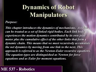
Rotary Jointed Arms • Overview • Rotary Jointed Arms work on the basic principle of the human arm. • They have a wrist, a shoulder, and an elbow. • Depending on what the robotic arm is used for, a gripper, like that of a hand can be added to the end of the arm, and ultimately give the user 3 axes of motion, generally referred to as pitch, yaw, and roll. • Pros • Allows for 3 axes of motion • Can emulate the human arm • Great idea when gripping objects is required • Cons • Large moments can develop at the shoulder and base plate, which can ultimately lead to failure of the joint. • A motor is required at each joint, and each has to be operated independently • Programming a system to work on several independent motors can be quite tricky 21
Combined Mechanisms • Overview • When one system doesn’t cut it, combining the mechanisms might help. • You may need reach, but the 4 bar doesn’t reach that high. • Attaching a 4 bar to a telescoping lift might be your answer. • Pros • Combines the pros of the various mechanisms • Cons • Complex 22
Four Bar Lifting Mechanism • Overview • The 4 bar mechanism is simple and effective. • The opposite bars always remain parallel retaining the orientation of the object. • Many industrial robots use this mechanism.
4 Bar Lifting Mechanism • Pros • Simple • Object retains orientation • 1 joint to power • Easily programmed • Provides reach • Cons • Large moments can develop at the joint location • Pin Loadings can be high • Required to lift “outside of the box” • Can be vulnerable to side hits • Tips • Watch for buckling in lower member • If possible, counterbalance • Keep the center of gravity (CG) aft 24
Multi-Bar Mechanisms Crossed 8 bar
Multi-Bar Mechanisms Parallel 8 bar
Arms Can reach over objects Can help right a flipped robot Can fold down to allow moving through barriers Require complex controls and counter-balances Harder to maintain CG over base Need space to swing up Need extra joints to reach higher which adds more complexity Lifts Limited reach Can't not help right a flipped robot Stay tall limiting movement through barriers Simple controls Maintain a better CG over the base Can operaet in confined spaces Lifts can reach higher with minimal added complexity Arms vs. Extension Lifts
Handling Objects Manipulation Storage Acquisition Size Placement and Alignment Accumulators Conveyers
Ball Manipulation • Both Continuous intakes and single object grabbers are useful when manipulating small or medium sized balls. • Types of Manipulators for Balls • Two tank treads horizontally or vertically aligned. • Three and Four Pronged Grabber • Two Point Grabber/ Fork • Bucket Intake • Roller • Should be soft grip to be able to effectively control and contain the ball. 29
Ring Manipulation • Both Continuous intakes and single object grabbers are useful when manipulating small or medium sized rings. • Types of Manipulators for Rings • Two tank treads horizontally or vertically aligned. • Three and Four Point Grabber • Two Point Grabber/ Fork • Bucket Intake • Roller • Should be soft grip to be able to effectively control and contain the Ring. 30
Square Manipulation • Both Continuous and single object grabbers are useful when manipulating small or medium sized squares. • Types of Manipulators for Squares: • Three and Four Pronged Grabber with Grip • Two Point Grabber • Should be a strong grip to be able to effectively control and contain the square. 31
Triangle Manipulation • Single object grabbers are useful when manipulating triangles. • Types of Manipulators for Triangles: • Three and Four Point Grabber • Flat Bottom and X Shaped Intake Roller • Should be strong grip to be able to effectively control and contain the Triangle. 32
Storing Objects • All items of the same size can be similar • Storage Method • Stack • Tank Tread • Divide • Dump Tank • Or Simple Grab and Drop to Goal 33
Storing Manipulator Arm • This must be decided with the base so the arm and manipulator have a place to go when a) trying to fit the size and b) to effectively pick up the objects • Storage Method • U Shaped Base • 360` Pivot Joint (and Arm Extender) • Manipulator Attached to Base 34
Acquisition Size • Acquisition is the intake area of the object. • Large acquisition area is optimal when picking up • During match, need easiest and quickest pick up for driver • Able to get the most amount of objects at once • When deciding acquisition intake, keep in mind what object you’re manipulating. 35
Placement and Alignment • Along with the acquisition zone, the placement of the object on/into the goal must be able to have accuracy with ease. • Along with the storage of the arm, you must work with the drive train to be able to fit the robot against the goal for optimal stability (Unable to be pushed away from the goal when attempting to score) and accuracy. • Alignment is the drive train’s responsibility. Make sure they know exactly how your mechanism works and where it needs to be positioned to make a goal. • Placement must be easy to work from a drivers standpoint. In contrast to the large acquisition zone, the manipulator should be small enough to accurately place the object on or in. 36
Gripping Objects • Why is the grip important? • The manipulator cannot effectively hold on to the object if both the object and the manipulator have no grip. • You need friction. • Friction is the force that opposes the relative motion or tendency toward such motion of two surfaces in contact • In this case, the force that opposes is gravity and the two surfaces are the manipulator and the object. 37
Mechanisms Motors and Servos Limits
Motors and Servos • The Motors and Servos make the arm and manipulator move. • Motors can turn a shaft* clockwise and counterclockwise as many degrees as desired. • Motors are generally used for continuous intake. • Servos can only turn a shaft* 180 degrees in either direction (360 degrees in total) • Servos should be used on < 360 degree pivot joints for both the arm and the manipulator. • *The shaft allows the motor to connect to the arm for a powered pivot point. 39
Limits • There are two types of stops: • Hard stop • The hard stop is a sturdy metal part of the robot’s structure. • This does not allow the manipulator / arm to go any farther. • However, the hard stop does not tell the motors to stop working, thus, the motors will break. • This is why we have soft stops. • Soft stop • Soft stops are limit switches. • When programmed correctly, the limit switch tells the motor or servo to stop. • Limits should be placed anywhere that contains a hard stop. • i.e. Arm pivot joints, two+ prong gabber, fork lifts, etc. 40
Gear Ratio • “There is no way that this motor can pull the arm and manipulator up against gravity. It’s just too heavy.” • If the motor is expected to work against a lot of weight, gear the ratio down. • i.e. 1:2 meaning for every one shaft revolution (360 degrees), the motor does two. • If the motor is not expected to work against a lot of weight and work quickly, gear the ratio up. • i.e. 2:1 meaning for every two shaft revolutions (two * 360 degrees), the motor does one. • However, you must have enough torque to pull the arm and manipulator up and down. • You must also have enough torque to keep hold on the object the robot is manipulating. It is not just friction holding it there. 42
Gear Ratio Calculations • The gear ratio is the relationship between the number of teeth on two gears that are meshed or two sprockets connected with a common roller chain, or the circumferences of two pulleys connected with a drive belt. D d
Force • In mechanics, forces are seen as the causes of linear motion • Forces are vector quantities, • They require vector math • Magnitude and a direction must be specified for a vector quantity • The SI unit for force is the Newton • Newton = kg m/s2
AB A B D C+D C E -E Vectors • Geometric object with magnitude and a direction • Represented by a line segment connecting the initial point A with the terminal point B • Vector Math • Addition • Tip to toe method • C+D • Subtraction • Flip the direction of vector
Hypotenuse Opposite θ Adjacent Angles • Measuring angles • Trigonometry • Note: Units in Radians. • Radians to Degrees 180° = π rad
x2 xcm Center of mass x1 Introduction – Center of Mass • Unique point in an object or system which can be used to describe the system's response to external forces and torques. • The concept of the center of mass is that of an average of the masses factored by their distances from a reference point.
Friction • Friction is the force resisting the relative motion of two surfaces in contact • The heavier an object is the larger the frictional force • The material on which the object is sliding also affects the frictional force.
10 lbs Power • Example #1 - Lifting Power = 100W Motor w/ 1” sprocket