Download
1 / 55
550 likes | 689 Vues
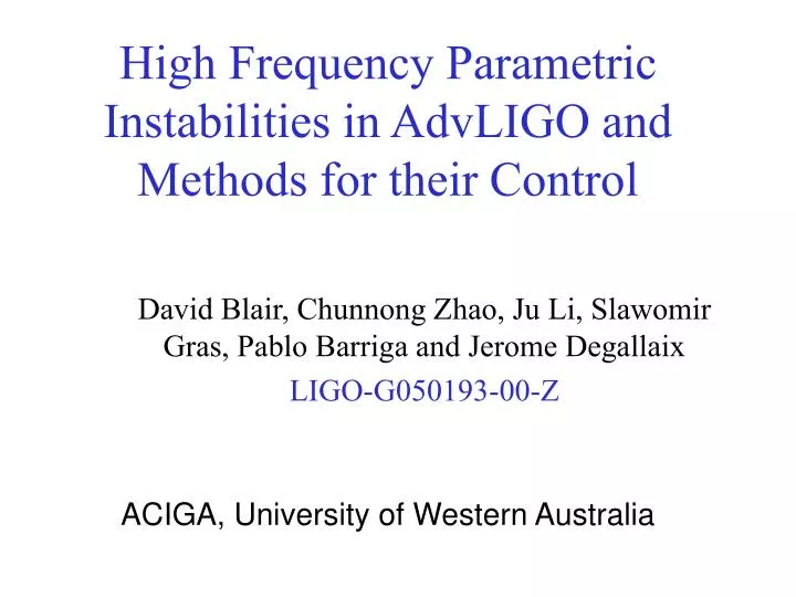
High Frequency Parametric Instabilities in AdvLIGO and Methods for their Control. David Blair, Chunnong Zhao, Ju Li, Slawomir Gras, Pablo Barriga and Jerome Degallaix LIGO-G050193-00-Z. ACIGA, University of Western Australia. PRL In press. Control Issues.

E N D
High Frequency Parametric Instabilities in AdvLIGO and Methods for their Control David Blair, Chunnong Zhao, Ju Li, Slawomir Gras, Pablo Barriga and Jerome Degallaix LIGO-G050193-00-Z ACIGA, University of Western Australia
PRL In press Control Issues
When energy densities get high things go unstable… • intrinsic coherent scattering • acoustic gain like a laser gain medium • akin to SBS • observed and controlled in NIOBE • not control system feedback instability!
Photon-Phonon Scattering up-conversion down-conversion Phonon Phonon absorption emission • Instabilities from photon-phonon scattering. • A test mass phonon can be absorbedby the photon, increasing the photon energy,(damping) • The photon can emit the phonon, decreasing the photon energy.(potential acoustic instability)
Two Types of Parametric Instability • Low Frequency: Phonon frequency is within the optical cavity bandwidth • optical spring effects affecting control and locking of suspended test masses • tranquilliser cavity to suppress high frequency instabilities • High Frequency: Phonon frequency outside optical cavity bandwidth • only possible if appropriate Stokes modes exist.
Schematic of HF Parametric Instability Radiation pressure force input frequency wo Stimulated scattering into HOM w1 Cavity Fundamental mode (Stored energy wo) Acoustic mode wm
Overlap factor Parametric Gain Half bandwidth of the optical mode Optical Q-factor Mechanical Q-factor Fundamental mode frequency High order transverse mode frequency Acoustic mode frequency High circulating power High optical and mechanical Q High overlap factor small, L > 0 R>1, Instabilities
Instability Requirements Frequency Coincidence Mode Shape Overlap L
Mode Density, Sapphire and Silica 20 modes / kHz 750/500 – the total number of modes at the end of the plot
Mode Structure for Advanced LIGO If Dw-wm< optical linewidth resonance condition may be obtained Dw = (n*FSR –TEMmn) - frequency difference between the main and Stokes/anti-Stokes modes wm -acoustic mode frequency, δ - relaxation rate of TEM
Example of acoustic and optical modes for Al2O3 AdvLIGO 44.663 kHz 47.276 kHz 89.450kHz acoustic mode HGM12 HGM30 LGM20 optical mode L 0.203 0.607 0.800 Loverlapping parameter If L >10-4 and Dw-wm = 0, R > 1 for AdvLIGO
4.6 kHz DfTEM = 0 kHz Dfax 1 2 3 4 5 Original AdvLIGO design HOM Df=4.6kHz R = 54416 m gmirrors = 0.926 0 f [kHz] 0 37.47 74.95 HOM not symmetric: Upconversion or down conversion occur separately. Down conversion always potentially unstable.
DfTEM = 0 kHz Dfax 1 2 3 4 5 Adv LIGO Nominal parameters HOM Df=4.6kHz R = 2076.5 m gmirrors = -0.926 4.6 kHz 0 f [kHz] 0 37.47 74.95
Is there a better choice of g-factor? AdvLIGO 100kHz 1/2FSR g-factor 10kHz Df for HOM 1kHz mirror radius of curvature, (m)
Comparison of Instabilities in Fused Silica and Sapphire Silica has ~ 7 times more unstable modes, worse instability gain Fine ROC tuning can reduce problem
AdvLIGO near current design Number of Unstable modes Maximum R-factor The maximum R of all acoustic modes (red) and number of acoustic modes (R>1, blue) as a function of mirror radius of curvature for fused silica.
AdvLIGO Long ROC Design number of unstable modes Maximum R of all unstable modes maximum R of all acoustic modes The maximum R of all acoustic modes (red) and number of acoustic modes (R>1, blue) as a function of mirror radius of curvature for fused silica
AdvLIGO Near Current for Sapphire Number of Unstable modes Maximum Parametric Gain The maximum R of all acoustic modes (red) and number of acoustic modes (R>1, blue) as a function of mirror radius of curvature for sapphire
AdvLIGO Long ROC Design, sapphire Maximum Parametric Gain Number of Unstable Modes The maximum R of all acoustic modes (red) and number of acoustic modes (R>1, blue) as a function of mirror radius of curvature for sapphire.
Thermal Tuning of ROC and Parametric Gain, Sapphire The dependence of the relative parametric gain R (dotted line) and the mirror radius of curvature (solid line) on the maximum temperature difference across the test mass if considering only one acoustic mode, for sapphire Unfortunately many acoustic modes mean cannot achieve such reduction
Thermal Tuning of Parametric Gain and ROC, Fused Silica The dependence of the relative parametric gain R (dotted line) and the mirror radius of curvature (solid line) on the maximum temperature difference across the test mass if considering only one acoustic mode, for fused silica
Conclusion so Far • Parametric instability is inevitable • Can be minimised by thermal tuning • Fused Silica has many more unstable modes • Best case 2 modes per test mass, R ~ 10 • Typical case (at switch on…and remember thermal lensing is changing R dynamically after switch on): R~100, 7-10 modes per test mass) 30-40 modes in all. • Is it possible to thermally tune to minimum before all hell breaks out?
Instability Control • Thermal tuning to minimise gain • complete control for sapphire, reduction for fused silica • Gain Reduction by Mechanical Q-Reduction • Apply surface losses to reduce Q without degrading thermal noise • Tranquilisation with separate optical system • Direct radiation pressure with walk-off beam • tranquiliser cavity (short cavity parametric stabiliser) • capacitive local control feedback • Re-injection of phase shifted HOM • Needs external optics only
Is power loss from ETM tuning a problem? • Power loss reasonably small c/w PRC transmission loss • Arm cavity power loss due to mode mismatching less than ~ 0.5% • (arm cavity only, not coupled with the power recycling cavity) • This results is to compared with the transmission of the PRC mirror 0.06
Less than 1% Power Loss due to Mode Mismatches if ETM is Tuned
Instability Ring-Up Time For R > 1, Ring-up time constant is ~ tm/(R-1) Time to ring from thermal amplitude to cavity position bandwidth (10-14m to 10-9 m is ~140tm/R ~ 100-1000 sec. Interferometer lock will be broken for amplitudes greater than position bandwidth. To prevent breaking of interferometer lock cavities must be controlled within ~100 seconds
Instability Control • Thermal tuning to minimise gain • complete control for sapphire, reduction for fused silica • Gain Reduction by Mechanical Q-Reduction • Apply surface losses to reduce Q without degrading thermal noise • Tranquilisation with separate optical system • Direct radiation pressure with walk-off beam • tranquiliser cavity (short cavity parametric stabiliser) • capacitive local control • Re-injection of phase shifted HOM • Needs external optics only
Instability Control By Direct Injection Cold Damping No Internal Components HOM Mode Matching needs to be modelled
Direct Cold Dampingby Feedback of HOM Signal • HOM signal can by definition transmit in arm cavity • HOM signal is also transmitted by PRC because it has a linewidth of ~MHz. BS laser 1/2wp QMod Feedback instability signal as angular modulation in orthogonal polarisation Readout instability PID Demod
Instability Control by Parametric Cold damping • Tranquiliser Cavity : small short cavity against test mass. BW ~ 1MHz, offset locked to enhance up-conversion=cold damping • Now being tested at UWA • Adds complexity with additional internal optical components, stabilised lasers etc
Instability Control by Direct Radiation Pressure Actuation • Demonstrated non-resonant radiation pressure actuation at UWA (walk off delay line) • Adds internal complexity • Possible shot noise and intensity noise problems
Instability control by local control feedback • Needs direct actuation on test mass • Capacitive actuation being tested at Gingin
Gingin Prediction 100 10 Maximum R of all acoustic modes 1 0.1 718 719 720 721 722 Radius of Curvature (m)
Conclusion • Braginsky was right…parametric instabilities are inevitable. • Thermal tuning can minimise instabilities but may be too slow in fused silica. • Sapphire ETM gives fast control and reduces total unstable modes from ~28 to 14 (average), • Can be actively controlled by various schemes • Reinjection Damping allows damping without adding internal complexity. • Gingin HOPF is an ideal test bed for these schemes.
4.6kHz DfTEM = 0 kHz 18.7 kHz Dfax 1 2 3 4 5 R = 2076.5 m gmirrors = -0.926 0 f [kHz] 0 37.47 74.95 Con-focal !
DfTEM = 0 kHz Dfax 1 2 3 4 5 R = 54416 m gmirrors = 0.926 0 f [kHz] 0 37.47 74.95 Near Planar !
4.6 kHz DfTEM = 0 kHz Dfax 1 2 3 4 5 R = 4000 m gmirrors = 0 0 f [kHz] 0 37.47 74.95
DfTEM = 0 kHz Dfax 1 2 3 4 5 R = 2000 m gmirrors = -1 4.6 kHz 0 f [kHz] 0 37.47 74.95
ETM heated by the non reflective side • (side outside the arm cavity) • Steady state deformations only depend on the heating power not on the heat pattern • However the test mass deformations evolution depends on the heat pattern • In the previous example, after 1 minute we reach the steady state value for sapphire against ~ 25 minutes for fused silica • An optimal time dependent heating power must exist to reach steady state quickly (faster for sapphire)
AIGO An Experiment to Investigate Parametric instabilities in High Power Cavities C.Zhao, L. Ju, S. Gras, J. Degallaix, and D. G. Blair School of Physics, The University of Western Australia Introduction: • Advanced laser interferometric gravitational wave detectors require very high laser power (~ 1 MW)to approach (or beat) the standard quantum limit as well as high mechanical Q-factor test masses to reduce the thermal noise. • Parametric instability is inevitable in advanced interferometric GW detectors which will make them inoperable. • We have predicted that parametric instabilities can be controlled by thermal tuning. • Australian Consortium for Interferometric Gravitational Astronomy (ACIGA) high optical power research interferometer will enable observation of this phenomena and the implementation of the control scheme. Photon–phonon scattering Conditions for instability Non-linear coupling between the cavity optical modes and the acoustic modes of the mirror *. Overlap factor Parametric Gain Half bandwidth of the optical mode Radiation pressure force Photon Photon Photon Photon Optical Q-factor Circulating Power Mechanical Q-factor Phonon Phonon Acoustic mode Cavity Fundamental mode (Stores energy ) Stimulated scattering Fundamental mode frequency High order transverse mode frequency Acoustic mode frequency (a) absorption (b) emission Main optical modes ( w0) Scattering Main optical modes ( w0) • Instabilities arise from photon-phonon scattering. A photon interacts with a test mass phonon, whereby • (a) A test mass phonon can be absorbed by the photon, increasing the photon energy, • (b) The photon can emit the phonon, decreasing the photon energy. • If (b) exceeds (a) instabilities can occur. High circulating power High optical and mechanical Q High overlap factor -> 0 Acoustic modes ( wm) Higher order optical modes ( w1) R>1, Instabilities Pumped by radiation pressure force Nominal Parameters of ACIGA Interferometer Thermal Tunning of the Radius of curvature Control the parametric instability With other parameters constant, increasing || will reduce parametric gain, R. Notes: L is the optical cavity length, g1,2 = 1-L/r1,2 are the cavity g-factors and r1,2 are the mirror radii of curvature, FSR is the cavity Free Spectral Range, m is the test mass’s mass (b) The temperature distribution inside the test mass with 5 W heating power. (a) The ANSYS model of a test mass with a heating ring at the back. Parametric Gain R=11 Thermally tuning the radii of curvature, r1 and/or r2, then g1 and/or g2, will change the optical mode spacing and the high order transverse mode frequency, 1. In consequences, || is increased. (b) (a) It is possible to reduce R to less than unity and eliminate the parametric instability completely (a) Radius of curvature as a function of the test mass temperature; (b) The relative parametric gain as a function of the radius of curvature considering only single acoustic mode. (a) A typical test mass acoustic mode structure, and (b) the first order transverse mode field distribution, showing high overlap between acoustic and optical modes. • Conclusions: • The parametric instability will appear in ACIGA’s high optical power research interferometer at Gingin, WA. • By thermally tuning the radius of curvature the parametric instability can be completely eliminated at ACIGA interferometer as does Advanced LIGO with sapphire test masses. • The extra components for the control is simply a heating ring at back of the end test mass. • The control scheme with thermal tuning tested on ACIGA interferometer at Gingin can be extended to Advanced GW detectors, such as Advanced LIGO. The maximum parametric gain of all acoustic modes when tuning the mirror radius of curvature The maximum parametric gain as a function of the radius of curvature, (a) Gingin cavity, (b) Advanced LIGO with sapphire test masses, and (c) fused silica test masses. It can be seen that with sapphire test masses in the Gingin cavity and Advanced LIGO the parametric instability can be eliminated. In the case of fused silica test masses in Advanced LIGO the parametric gain can be minimised but not eliminated. (a) ACIGA interferometer with sapphire test masses (c) Advanced LIGO with fused silica test masses (b) Advanced LIGO with Sapphire Test masses * Braginsky, et al, Phys. Lett. A, 305 111 (2002)