Download

1 / 22
220 likes | 435 Vues
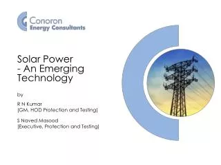
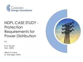
CASE STUDIES - PROTECTION OF POWER DISTRIBUTION SYSTEM - I by R. N. Kumar GM , NDPL. CASE STUDY 1 Tripping Analysis for fault on 11 KV Swatantra Nagar Feeder at Ghogha Mod in Zone 514 (NRL). Ghoga KIosk S/Stn. Swatantra Nagar Feeder. /. /. X. Schneider make RN2C RMU.

E N D
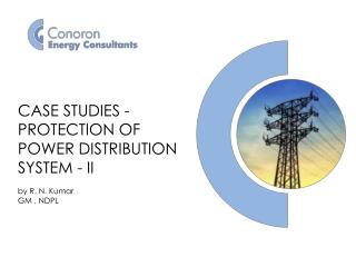
CASE STUDIES - PROTECTION OF POWER DISTRIBUTION SYSTEM - I by R. N. KumarGM , NDPL
CASE STUDY 1 Tripping Analysis for fault on 11 KV Swatantra Nagar Feeder at Ghogha Mod in Zone 514 (NRL)
Ghoga KIosk S/Stn Swatantra Nagar Feeder / / X Schneider make RN2C RMU Bawana CWW Grid S/Stn X Holambi Nagar Feeder A / R Sectionalizer Sectionalizer Sectionalizer 3
Occurrences • Auto Recloser Locked out • Sectionalizer did not trip • Fuses of the DT’s were getting blown off • The fault was of transient nature. It happened three to four times • Load on the feeder was found more than 250 Amps • Observations • Relay settings of RMU at kiosk S/Stn are found as per approved relay settings. • Relay setting of AR are also found as per the approved relay settings.. • Auto recloser relay settings were 180Amps for O/C and 100Amps for E/F elements. • Sectionalizers current settings were 500Amps. • Fault current was found between 350 Amps to 450 Amps as per relay data. 4
Investigations • Auto recloser was working properly • Load on the feeder was detected more than the O/C set value of Auto Recloser relay • Sectionalizers current setting was more than that of the fault current , hence never isolated the faulty feeder • Fuses were under rated • CAPA • The Auto Recloser O/C current setting was enhanced from 180 Amps to 200 Amps • The Auto Recloser E/F current setting was enhanced from 100 Amps to 150 Amps • The Sectionalizers current setting was reduced to 275Amps from 500Amps. • Zonal staff was asked to reduce the load on the feeder and install proper/standard rating of the fuses on the DT’s. 4
Sudarshan Park grid Gadaria S/Stn Achpal S/Stn Rattan Park S/Stn Ramgarh S/Stn Single Line Diagram Trip X X Trip Trip Basai Darapur X F 7
S/Stn Gadaria S/Stn Achpal / / / / / / Schneider RN2C VIP300 ABB ,WIC1 X X X X I/C Sudarshan Park Grid I/C Bali Nagar O/G Achpal I/C Gadaria O/G Rattan Park 630 KVA 1000 KVA 2X250 KVA DT S/Stn Rattan Park Schneider RM6 VIP300 / / / / X X X X I/C Achpal Tie Spare O/G Ram Garh I/C Bali Nagar 630 KVA 630 KVA S/Stn Ram Garh CG Lucy WIP1 / / / / X X I/C Rattan Park O/G Old Bsai Dara Pur O/G Achpal 630 KVA 8
Occurence • For any fault beyond Ramgarh S/Stn, O/G CB of all the S/Stns in this circuit were getting tripped in cascading. • INVESTIGATIONS • As per protection philosophy circuit breaker is required to be installed only at first switching S/station for O/G feeder • Purpose of RMU is defeated • Cascade tripping of circuit breakers installed in series can not be avoided as there is a little time margin to discriminate between these breakers • CAPA • Zonal staff has been advised to connect the O/G feeder of the S/Station other than that of First Switching S/Station (Rattan Park S/Station) on isolator to avoid cascade tripping of breakers. 9
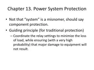
Occurrence Power Transformer tripping on Differential Protection Observations The Numerical relay indicated that Transformer has tripped on Saturation Discrimination element in Differential Relay. 11
Investigations • A new feature of Saturation Discrimination has been added in relay to pinpoint tripping of the transformer due to saturation of CT Cores. Saturation of CT Cores causes flow of differential current through operating coil of the relay. • In CT Saturated condition, tripping generally occurs when transformer is loaded up 50 to 75% loading capacity. At this load current discrimination is sufficient enough to cause tripping. • Findings • Knee point voltage of PS Class CT Core has got reduced on account of Saturation. • Difference of Saturation curve is indicated in Diagram. • Tripping current waveforms also shows fault details. • CAPA • Saturated CT’s were replaced • All three CT’s were replaced to keep Identical CT Magnetizing curve 12
CT SATURATION AT 33 KV AIR KHAMPUR GRID SATURATED CORES 13
CASE STUDY 4 Tripping of 11 KV Incomer-2 Tripping without indication on Outgoing fault in 33 KV
C11 C31 C51 C71 => CDG Relay NC contact. => CDG relay Coil => Series Trip Coil Observations 1. It was found that at high currents with unbalance, the 11 kV Incomer-2 was tripping without indication.2. It was found that the tripping was occurring through series trip coil mounted on the 11 kV Incomer breaker.3. It was found that the series trip relay (CDG), though not operated gave a trip signal to the breaker when secondary injection was carried out on Phase to neutral CT.4. On checking the wiring of the series trip relay and the tripping circuit, one wire was found broken as shown in diagram. Breaker was tripping through series trip coil which was operating on spill current due to unbalance in system. Analysis For Wazirabad Inc. 2 tripping without indication during outgoing fault. 16
Conclusion & Corrective Action 1. As the interconnection between NC Contact and Neutral terminal was disconnected due to defective lug crimping, the unbalance current, whenever present, was not being bypassed by the NC contact of the relay. Instead, the current was going through the series trip coil, thereby making relay settings redundant. This was leading to the tripping of 11 kV Inc.2 breaker tripping on any unbalance or fault.2. Necessary correction wiring of contacts was done and Unbalance was simulated to check the correct operation of the relay .Now Control circuit and relay functionality found OK. 17
CASE STUDY 5 Tripping Analysis report for 11 KV Mithila Vihar feeder along with 11 KV Incomer
Case Study • Tripping Analysis report for 11 KV MithilaVihar feeder alongwith 11 KV Incomer • Details of Event • 11 KV MithilaVihar feeder tripped alongwith 11 KV Incomer • Observations • Total load of the station is around 800 Amps and System is keeping total load on any of the transformer keeping the other transformer on no load. • MithilaVihar feeder tripped on over current High set. • 11 KV Incomer-2 tripped on over current High set. • Fault data record of the Incomer show’s that Fault seen by 11 KV • Incomer is 9.1 KA while fault seen by MithilaVihar feeder is 6.2 KA. • It is observed that Nithari feeder was also seen the fault but not tripped due to isolation of the fault. Protection settings were Coordinated and CT Ratio adoption was found correct. 20
Conclusions After going through the tripping events it was observed that both feeders were getting tripped simultaneously. After going through the fault data record, it is very clear that fault seen by Incomer is always on higher side as compared to the outgoing feeder. The tripping in the incomer occurs as the fault current “seen” by the incomer breaker is a summation of the outgoing faults. It has been learnt from Concerned Zonal staff, that both the outgoing feeders in question, viz. MithilaVihar feeder and Nithari feeder, are routed on the same poles and on same cross arm. Thereby, the occurrences of birdages in both the feeders occur simultaneously. 21