Download

1 / 24
300 likes | 923 Vues
CE En 112 Engineering Drawing with CAD Application. Chapter 2: Sketching and Text (Lecture D) Pictorial Drawings. Lecture Outline. Objectives Introduction (2.4, p.85) Isometric drawings (2.4.1, p.87) Oblique drawings (2.4, p.86) Perspective drawings (2.7, p.104) Next class. Objectives.

E N D
CE En 112 Engineering Drawing with CAD Application Chapter 2: Sketching and Text (Lecture D) Pictorial Drawings
Lecture Outline • Objectives • Introduction (2.4, p.85) • Isometric drawings (2.4.1, p.87) • Oblique drawings (2.4, p.86) • Perspective drawings (2.7, p.104) • Next class
Objectives • Learn how to construct three types of pictorial drawings: 1) Isometric 2) Oblique 3) Perspective
Introduction • Comparison of Isometric, oblique, and perspective drawings
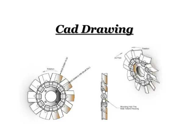
Perspective Oblique Introduction (con’t) • Examples:
Isometric Drawings (2.4) • An axonometric pictorial drawing for which the angle between axes equals 120 degrees and the scale used is full scale • Isometric axes can be positioned in a number of ways to create different views of the same object • Regular isometric is the most common type
Isometric Drawings (con’t) • True length distances can only be measured along isometric lines, that is, lines that run parallel to any of the isometric axes
Hidden lines are omitted unless absolutely necessary to describe the object Center lines are drawn for showing symmetry or for dimensioning – normally they are not shown Isometric Drawings (con’t) Example: Center Lines for Dimensioning Example: Hidden Lines Necessary for Details
Isometric Drawings (con’t) • Dimensioning for production purposes: • Dimensions per ANSI standards • Dimension lines, extension lines, and lines dimensioned shall lie in the same plan • All dimensions and notes should be unidirectional, reading from the bottom upward and outside the view
Isometric Drawings (con’t) • Dimensioning for illustration purposes: • Use the aligned method • Dimension lines, extension lines, and lettering are all draw in the plane of one of the faces of the object • Takes on more of a pictorial look
Isometric Drawings (con’t) • Constructing an isometric drawing using the Boxing-In Method: Box in from the outmost shape to inside details
Isometric Drawings (con’t) • What if you have non-isometric lines? Remember that true-length distances can only be measured along isometric lines, that is, lines that run parallel to any of the isometric axes
Isometric Drawings (con’t) • What if you have curves? • Use the offset coordinate method
Oblique Drawings (2.4) • A form of pictorial drawing in which the most descriptive or natural view is treated as the front view and is placed parallel to the plane of projection • Typical oblique drawing angles are 30, 45, or 60 degrees from the horizontal
Oblique Drawings (con’t) • Three basic types of oblique drawings: • Cavalier: drawn true length along the receding axis • Cabinet: drawn half the true length along the receding axis • General: drawn anywhere from full to half length along the receding axis
Oblique Drawings (con’t) • In oblique projection, the object face that is placed parallel to the frontal plane will be drawn true size and shape • Thus, the first rule in creating an oblique drawing is to place complex features (i.e., arcs, holes, or irregular surfaces) parallel to the frontal plane
Oblique Drawings (con’t) • In oblique drawings, dimensions lie in the plane of the surface to which they apply, and unidirectional text placement is used Dimension text may need to be changed because only the cavalier oblique projection gives true depth.
Creating an Oblique sketch: Step 1: Block in the front face of the object. Estimate distances to create a proportioned sketch Step 2: Sketch depth construction lines at 30 to 45 degrees. Estimate depth along the sketched lines Step 3: Draw a line between each depth mark to create the back edge Step 4: Darken all visible lines including any part of a back circle that is inside a front circle Oblique Drawings (con’t)
Perspective Drawings (2.7) • Pictorial drawings used to represent 3-D forms on 2-D media in a manner closest to how we perceive the objects with our eyes • Terms to be familiar with include horizon line (HL), ground line (GL), station point (SP), picture plane (projection plane), and vanishing point (VP)
Perspective Drawings (con’t) • The view of the object can be dramatically changed by moving the vanishing point along the horizon line • Points to the right of center will reveal details about the right side of the object; while points to the left of center will reveal details about the left side
The human’s eye view is the most commonly used for sketching everyday objects The position of the view has a dramatic effect on the representation of the drawing Perspective Drawings (con’t)
Perspective view drawings can be one-, two-, or three-point perspectives Four variables to consider in perspective view drawings: Distance of object from picture plane Position of station point Position of ground line Number of vanishing points Perspective Drawings (con’t) Practice creating a one-point perspective sketch (Fig. 2.54 in text)
Next Class • Section Views • MD HW3 will be assigned.