Download
1 / 23
230 likes | 259 Vues
Explore how Faraday rotation in the ionosphere impacts SAR data quality and learn methods for calibration and validation.

E N D
The Ionosphere and Interferometric/Polarimetric SAR Tony Freeman Earth Science Research and Advanced Concepts Manager
Surface Clutter Problem • Repeat-pass Interferometry • Subsurface return has phase difference 1 due to ionosphere propagation (same as surface return from location O) • Surface clutter return (from location P) has phase difference 2 due to ionosphere propagation • So 1 - 2 is unknown - could be zero - depends on correlation length of ionosphere • Is 1 - 2 variable within a data acquisition? (Probably) Radar Ionosphere r2+r+2 r1 r2 +1 r1+r i O P r r z Q
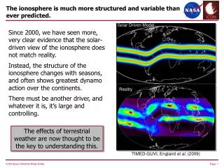
Ionospheric Effects Two-way propagation of the radar wave through the ionosphere causes several disturbances in the received signal, the most significant of which are degraded resolution and distorted polarization signatures because of Faraday rotation. Except at the highest TEC levels, the 100 m spatial resolution of CARISMA should be readily achievable [Ishimura et al, 1999]. Faraday rotation in circular polarization measurements is manifested as a phase difference between the R-L and L-R backscatter measurements. If this phase difference is left uncorrected, it is not possible to successfully convert from a circular into a linear polarization basis – the resulting linear polarization measurements will still exhibit the characteristics of Faraday rotation. The need to transform to a linear basis stems from CARISMA’s secondary science objectives – and the requirement to use HV backscatter measurements, which have exhibited the strongest correlation with forest biomass in multiple studies. As shown in [Bickel and Bates ,1965], [Freeman and Saatchi, 2004] and [Freeman, 2004] it is, in theory, relatively straightforward to estimate the Faraday rotation angle from fully polarimetric data in circularly polarized form, and to correct the R-L to L-R phase difference. Performing this correction will then allow transformation to a distortion-free linear polarization basis.
Calibration/Validation Calibration of the near-nadir radar measurements to achieve the primary science objectives of ice sheet sounding is relatively straightforward. The required 20 m height resolution matches the capability offered by the bandwidth available, and is easily verified for surface returns by comparison with existing DEMs. For the subsurface returns CARISMA measurements will be compared with GPR data, ice cores and airborne radar underflight data. The required radiometric accuracy of 1 dB is well within current radar system capabilities and can be verified using transponders and or targets with known (and stable) reflectivity. Radiometric errors introduced by external factors such as ionospheric fading and interference require further study. Calibration of the side-looking measurements over the ice is a little more challenging but the primary science objectives can still be met. Validation that the differentiation between surface and subsurface returns has been successful, will be carried out by simulating the surface ‘clutter’ using DEMs and backscatter models. Calibration of the side-looking measurements over forested areas will be yet more challenging. The techniques described in [Freeman, 2004] will be used to generate calibrated linear polarization measurements. Data acquired over targets of known, stable RCS, such as corner reflectors and dense tropical forest will be used to verify the calibration performance. Validation of biomass estimates and permafrost maps generated from CARISMA data will be carried out by comparison with data acquired in the field.
Introduction and Scope • Faraday rotation is a problem that needs to be taken into consideration for longer wavelength SAR’s • Worst-case predictions for Faraday rotation for three common wavebands:
Summary of Model Results • Spread of relative errors introduced into backscatter measurements across a wide range of measures for a diverse set of scatterer types • Effects considered negligible (i.e. less than desired calibration uncertainty*) are shaded • *Radiometric uncertainty - 0.5 dB • Phase error - 10 degrees • Correlation error - 6% • A Noise-equivalent sigma-naught of - 30dB is assumed
Estimating the Faraday Rotation Angle, W • Sensitivity to Residual System Calibration Errors (shaded cells represent errors in W > 3 degrees)
Estimating the Faraday Rotation Angle, W • Combining effects for a ‘typical’ set of system errors, we see that a cross-talk level < -30 dB is necessary to keep the error in W < 3 degrees using measure (2) For Measure (1) error is dominated by additive noise • P-Band case has channel amplitude imbalance of 0.5 dB, phase imbalance of 10 degrees and NE so = -30 dB • L-Band case has channel amplitude imbalance of 0.5 dB, phase imbalance of 10 degrees and NE so = -24 dB
Calibration Procedure for Polarimetric SAR data • (Cannot estimate cross-talk from data) • (Use any target with reflection symmetry to ‘symmetrize’ data) • (Trihedral signature or known channel imbalance) • Taking Faraday rotation and ‘typical’ system errors into account
Polarimetric Scattering ModelDistributed scatterers • Take a cross-product: • Take an ensemble average over a distributed area: • For uncorrelated surface and subsurface scatterers: No interdependence between surface and subsurface returns • Which leaves: • Similar arguments hold for other cross-products
Polarimetric Scattering ModelSurface-Subsurface correlation • Why should the scattering from the surface and subsurface layers be uncorrelated? • 3 reasons: • The scattering originates from different surfaces, with different roughness and dielectric properties • The incidence angles are very different (due to refraction) • The wavelength of the EM wave incident on each surface is also quite different, since
r r+r i P O r z r Q Geometry Radar mv(r), s, l, , i loss tangent, tan mv(r), s, l, , i
Inversion? Empirical Surface Scattering Model • For each layer we have 5 unknowns: mv(r), s, l, , i • For the surface return we know , and can estimate i if we know the local topography and the imaging geometry • For the subsurface scattering, the wavelength is a function of the dielectric constant for the layer, i.e. • In addition the attenuation of the subsurface return is governed by: tan , r • - This still leaves a total of 9 unknowns • Under the assumptions of reciprocity (HV = VH), and that like- and cross-pol returns are uncorrelated, we can extract just 5 measurements from the cross-products formed from the scattering matrix • ==> Inversion is not possible
Interferometric Formulation • Correlation coeff: ? = 2.5 = 4.0
Interferometric Formulation • Correlation coeff: ~ invariant, as are , = 2.5 = 4.0
Surface Clutter Problem Subsurface scattering from i = 2.9 deg Surface clutter from i = 20 deg Radar r2+r r1 r2 r1+r i O P r r z Q
2-Layer Scattering ModelConclusions • Polarimetry: • Model derived from scattering matrix formulation indicates that there is no depth-dependent information contained in the polarimetric phase difference (or any cross-product) • Unless - surface and subsurface returns are correlated • Inversion of polarimetric data does not seem possible • Stick with circular polarization for a spaceborne system? • ==> Only problem is resolution, position shifts due to ray bending • Interferometry: • Behavior of the correlation coefficients for surface clutter and subsurface returns as a function of baseline length are different (assuming flat surfaces)