Download
1 / 17
170 likes | 201 Vues
Analyzing the material strength and safety factors of the Tilt N' Store structure through stress and shear calculations for arm, chain hoist support, frame leg, and anchor. Detailed conclusions on the factor of safety for each component. Pins' size, shear stress, bearing stress, and lubrication considerations discussed.

E N D
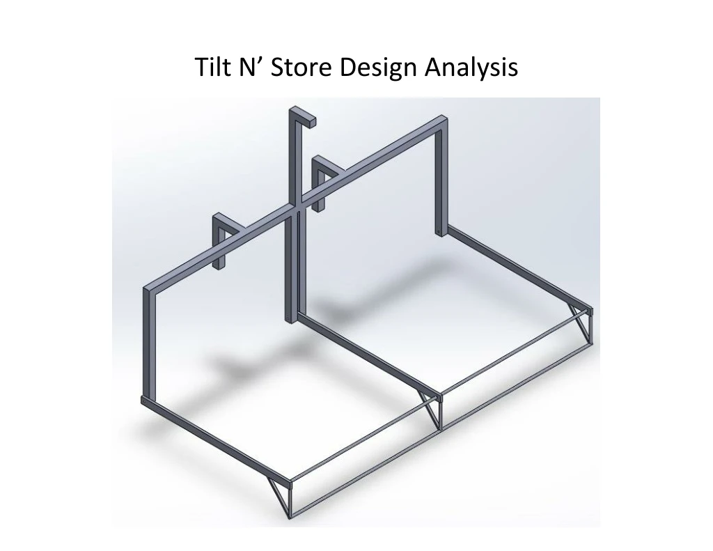
Chain Hoist Support Anchor Frame Frame Leg Bike Support Arm
Key Question: What Factor of Safety do we get assuming the Tilt N’ Store is built from the materials proposed in the Bill of Materials? Or will the Tilt N’ Store survive if built with the materials suggested?
Tilt N’ Store - Arm Figure 1: Free Body Diagram of Arm Table 1: Design Parameters Figure 2: Mechanical Advantage From Chain Hoist (MA = 25)
Tilt N’ Store - Arm Figure 3: Shear Diagram of Arm Figure 4: Bending Moment Diagram of Arm • Conclusions: • Normal Stress: • The Maximum Normal Stress due to Bending on the arm has a magnitude of 25,382 psi • The Factor of Safety given this Normal Stress is 1.42 • Shear Stress: • The Maximum Shear Stress on the arm has a magnitude of 1,000 psi • The Factor of Safety give this Shear Stress is 33.7
Tilt N’ Store - Chain Hoist Support Figure 5: Free Body Diagram of Chain Hoist Support Table 2: Design Parameters
Tilt N’ Store – Chain Hoist Support Figure 6: Shear Diagram of Chain Hoist Support Figure 7: Bending Moment Diagram of Chain Hoist Support • Conclusions: • Normal Stress: • The Maximum Normal Stress due to Bending on the support has a magnitude of 14,513 psi • The Factor of Safety given this Normal Stress is 2.48 • Shear Stress: • The Maximum Shear Stress on the support has a magnitude of 885.1 psi • The Factor of Safety give this Shear Stress is 38
Tilt N’ Store - Frame Leg Figure 8: Free Body Diagram of Frame Leg Table 3: Design Parameters
Tilt N’ Store – Frame Leg Figure 9: Shear Diagram of Frame Leg Figure 10: Bending Moment Diagram of Frame Leg • Conclusions: • Normal Stress: • The Maximum Normal Stress due to Bending on the frame leg has a magnitude of 0 psi • The Factor of Safety given this Normal Stress is Infinity • Shear Stress: • The Maximum Shear Stress on the frame leg has a magnitude of 0 psi • The Factor of Safety give this Shear Stress is Infinity
Tilt N’ Store - Anchor Figure 11: Free Body Diagram of Anchor Table 4: Design Parameters
Tilt N’ Store – Anchor (Vertical Support) Figure 12: Shear Diagram of Anchor (Vertical Support) Figure 13: Bending Moment Diagram of Anchor (Vertical Support) • Conclusions: • Normal Stress: • The Maximum Normal Stress due to Bending on the support has a magnitude of 1,712 psi • The Factor of Safety given this Normal Stress is 21 • Shear Stress: • The Maximum Shear Stress on the support has a magnitude of 443 psi • The Factor of Safety give this Shear Stress is 76
Tilt N’ Store – Anchor (Horizontal Support) Figure 14: Shear Diagram of Anchor (Horizontal Support) Figure 15: Bending Moment Diagram of Anchor (Horizontal Support) • Conclusions: • Normal Stress: • The Maximum Normal Stress due to Bending on the support has a magnitude of 3,108 psi • The Factor of Safety given this Normal Stress is 11.6 • Shear Stress: • The Maximum Shear Stress on the support has a magnitude of 1,658 psi • The Factor of Safety give this Shear Stress is 20
Tilt N’ Store - Frame Figure 16: Free Body Diagram of Anchor Table 5: Design Parameters
Tilt N’ Store – Frame Figure 17: Shear Diagram of Frame Figure 18: Bending Moment Diagram of Frame • Conclusions: • Normal Stress: • The Maximum Normal Stress due to Bending on the frame has a magnitude of 13,530 psi • The Factor of Safety given this Normal Stress is 2.66 • Shear Stress: • The Maximum Shear Stress on the frame has a magnitude of 835 psi • The Factor of Safety give this Shear Stress is 40.28
Tilt N’ Store – Pins • How large do the pins at the joints need to be in order to hold the weight? • The Maximum Shear Stress due to the reaction forces at the pins was calculated to be 4800psi using a steel bar with a 0.25” diameter. This yields a Factor of Safety of 7. • The Bearing Stress on the thinner beam is calculated to be 3000psi. A subject matter expert said a more in-depth approach to calculating bearing stress can be found in some more advanced literature. • Can we use a dry bearing or do we need to grease the pin? • After discussing this point with a subject matter expert, he recommended that we use a dry bearing. He believed the weight our system would encounter would not be enough to require a greased bearing. • He also recommended using bolts for cheaper cost and easier construction (More analysis to follow on the grade of bolt that needs to be selected). The evolution of the pins started at door hinges self-fabricated gate hinges Welded Rod Bolts. t Ry1 d D
Key Questions Answered: • What Factor of Safety do we get assuming the Tilt N’ Store is built from the materials proposed in the Bill of Materials? – Answered in previous slides • How large do the pins at the joints need to be in order to hold the weight? • -Answered in previous slides • Based on the material, can we use 3 beams? • Yes, the Factor of Safety is fine even with an exaggerated load. • What thickness do the steel walls need to be? • The analysis above was run assuming the arms have a wall thickness of 0.120” and the rest of the frame has a thickness of 1/8”. Both resulted in acceptable Factors of Safety • How much force do the safety ropes need to hold? • One safety rope holding a 100lb beam with 500lbs of Bikes at the end will need to hold ~2400lbs when attached at a 45 degree angle 2 feet from the pivot joint. Rope 45deg 2ft W Bike


