Download
1 / 24
350 likes | 1.43k Vues
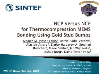
NCP Versus NCF for Thermocompression MEMS Bonding Using Gold Stud Bumps. Maaike M. Visser Taklo 1 , Astrid-Sofie Vardøy 1 , Alastair Attard 2 , Zlatko Hajdarevic 2 , Stephan Bulacher 2 , Mario Saliba 3 , Jan Wijgaerts 3 , Joshua Borg 4 , David Oscar Vella 4 1 SINTEF, Oslo, Norway

E N D
NCP Versus NCFfor Thermocompression MEMS Bonding Using Gold Stud Bumps Maaike M. Visser Taklo1, Astrid-Sofie Vardøy1, Alastair Attard2, Zlatko Hajdarevic2, Stephan Bulacher2, Mario Saliba3, Jan Wijgaerts3,Joshua Borg4, David Oscar Vella4 1SINTEF, Oslo, Norway 2Besi Austria GmbH, Radfeld, Austria 3Henkel, Westerlo, Belgium 4STMicroelectronics Malta, Kirkop, Malta
Abbreviations • NCP • Non Conductive Paste • NCF • Non Conductive Film www.henkel.com www.henkel.com www.besi.com
Au Stud Bump Bonding • e-CUBES 2006-2009 • Perfect for low I/O MEMS • Epoxy: automotive application • Capillary underfilled/pre-applied • Thermocompression/thermosonic • Epotek353ND • Lab4MEMS 2013-2015 • High volume process • MEMS with low I/O • Epoxy for consumer application • Pre-applied paste or film • No capillary based solutions considered RELIABILITY COST EFFICIENCY
Outline • Design, test samples • Design of Experiment (DoE) for assembly • Visual inspections • Shear testing • Cross sections and SEM/EDS • Conclusion and outlooks
Daughter die Adhesive Mother die on the larger substrate part Interface between the dies Design, test samples • Mother and daughter die configuration Assemblies 10 x 10 mm2 arrays mother dies 150 mm test wafers Single daughter dies Bumping Dicing 1 x 2 mm2
Bumping • On wafer scale Z1:63.5-68.8 µm Ø: 83.0-85.7 µm Z2: 26.1-28.7 µm Ø: 83.5-85.8 µm Standard bumps Accubumps™ FILM/ DICING
Film or paste • NCP • Dice daughter wafer • Deposit on mother wafer • Dispense NCP: Sequential • Stencil print NCP: Wafer level • Issue: "Pot life" after deposition • NCF • Lamination on daughter wafer, dice • Good control of amount of material • Dicing critical • Issue: "Pot life" after lamination Daughter NCP on mother NCF on daughter
Material • NCP Hysol FP5201, from Henkel • For thermal compression bonding, flip chip • Glass Transition Temperature (Tg) by TMA, 171 °C • DMA Modulus @ 25°C, GPa 5.8 • NCF CUF1166-99D, from Henkel • For Cu pillars and Au bumps, good transparency • Glass Transition Temperature (Tg) by TMA, 100 °C • DMA Modulus @ 25°C, GPa 4.2
NCP: Bond time and cure • Time for bonding, Bond Delay, varied • Temperature needed for bonding, TBond varied TAlign 150 oC Bond Delay 1-2 s TFlow 150 oC TBond 250-380 oC TInt-Bond TInt-Flow Tsubstrate70oC Tsubstrate70oC Tsubstrate70oC Q Q Post cure 30 min at 165 oC
DoE, NCP - paste Substrate (@70 oC) heat sink S: Standard bumps A: Accubumps™
NCF: Flow temperature • Temperature needed for flow, TFlow varied Soften 2 s Bond Delay 2 s TAlign Ramp 70 oC ▼100-180 oC TFlow 100-180 oC TBond 350 oC TInt-Bond TInt-Flow Tsubstrate70oC Tsubstrate70oC Tsubstrate70oC Q Q Post cure 40 min at 175 oC
DoE, NCF - film Substrate (@70 oC) heat sink Only Accubumps™ Bond Delay 2 s TBond 350 oC TInt-Bond 205 oC >15 "Legs" ready for characterization
Visual inspection I • Flow NCP Accubumps vs. Standard NCF • Fillet NCP NCF
Visual inspection II Standard Accubumps • NCP • NCF Accubumps Bond Line Thickness Tilt
Shear testing, NCP • 3 samples tested per "leg" • 95% confidence intervals calculated Accubumps 5 kg ~ 25 MPa
Shear testing, NCF • 3 samples tester per "leg" • 95% confidence intervals calculated Accubumps 5 kg ~ 25 MPa
Cross sectioning • Embedded in epoxy • Ground manually with SiC grit abrasive paper • Polished with colloidal diamond suspension • Down to 1 µm
Single bumps NCPAccubump 1 s, TBond 250 oC NCFAccubump 2 s, TFlow 100 oC Mother die Mother die
Metallurgic bonding • NCP • Accubumps, 2 s Bond Delay 380 oC 250 oC "More"
Trapped particles • Cracks/folded metal • Result of sample preparation • Or both…
EDS, materials • Studies at daughter die side Al Ni Cu Si SiO2 Al Ni Cu Au Au Si SiO2 Au
A gap with adhesive? • EDS mapping of C measured • Contrast increased in power point Apparently a gap not filled with adhesive, but challenging to prove, even in low vacuum
Summary • Satisfactory results, both NCP and NCF • Visual inspection • Shear strength • Cross sections • Electrical testing remains • A question of cost efficiency • Not necessarily the same answer for different applications
Acknowledgment • This work was supported by the Research Council of Norway and the ENIAC Joint Undertaking • Lab4MEMS, Grant Agreement no 325622-2 • Joachim Seland Graff for assistance with sample preparation and SEM