Download
1 / 21
210 likes | 350 Vues
Fermilab/ Beams Division/ Cryogenic department Ch. Darve, B. Norris, A. Martinez, L. Pei. Mucool Test Area Cryo-system Design. Main requirements for the cryo-system : Density fluctuation in the LH2 should be smaller than +/- 2.5 % P=1.2 atm=17.6 psia=0.12 MPa Subcool temperature => 17 K.

E N D
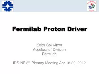
Fermilab/ Beams Division/ Cryogenic departmentCh. Darve, B. Norris, A. Martinez, L. Pei Mucool Test Area Cryo-system Design
Main requirements for the cryo-system: Density fluctuation in the LH2 should be smaller than +/- 2.5 % P=1.2 atm=17.6 psia=0.12 MPa Subcool temperature => 17 K FERMILAB BD/Cryogenic Department Part IV – A look at the Windows and Absorber Vessel Overview of the need for Liquid Hydrogen 1- Stay bellow boiling point 2- Temperature difference < 1 K (using a large safety factor) - in absorber volume - in the cryo-system MTA Cryo-system design - BNL review overview
FERMILAB BD/Cryogenic Department Part IV – A look at the Windows and Absorber Vessel Overview of MuCool Test Area cryo-system - cryostat MTA Cryo-system design - BNL review overview
The LH2 pump was designed and built by Caltech as a spare pump for the SAMPLE experiment (½ dia. of the pump used in E158) Purpose: To circulate LH2 in a close loop and provide force flow to remove the energy loss from the LH2 absorber, with DT<1 K Max. available flow at 17 K, 1.2 atm = 450 g/s Reference: “E.J. Beise et al., A high power liquid hydrogen target for parity violation experiments, Research instruments & methods in physics research (1996), 383-391” Schematic of SAMPLE FERMILAB BD/Cryogenic Department Part IV – A look at the Windows and Absorber Vessel Overview on the Absorber Pump flow method MTA Cryo-system design - BNL review overview
FERMILAB BD/Cryogenic Department Part IV – A look at the Windows and Absorber Vessel Overview on the Absorber Pump flow method • The LH2 pump is composed of: • two impeller blades => to straighten the flow • three stators => to accelerate the flow • two cones => to reduce the impedance of the flow • Materials: • Impellers: Aluminum 6061 T6 • Housing: 304 • A motor located at room temperature drive the pump: • typical Tevatron Wet Engine 2 HP motor will be used MTA Cryo-system design - BNL review overview
What is the mass flow needed to cool the beam? Simulation of the flow by Wing Lau/ Charles H. Holding(Oxford) using Algor 2 D model How to use the results? Determine velocity so that DT<1K FERMILAB BD/Cryogenic Department Part IV – A look at the Windows and Absorber Vessel Overview on the Absorber Pump flow method DT V • We determine the velocity, V, for the addoc temperature difference, DT: • m (for given DT, nozzle geometry and LH2 prop.) • DP(for LH2 cryoloop) SEE WING LAU TALK MTA Cryo-system design - BNL review overview
We do need to understand the thermo-hydraulic behavior of the LH2 absorber Example: Case of the maximum available flow by the LH2 pump In order to be functional the LH2 absorber would need to be optimized (goal: reduction of the pressure drop) Proposed changed: If V=4 m/s then m=450 g/s FERMILAB BD/Cryogenic Department Part IV – A look at the Windows and Absorber Vessel Overview on the Absorber Pump flow method Current geometry Requested geometry LH2 abs: Nozzle dia.= 0.43” 11 Supply nozzles 15 returns nozzles Piping in the magnet bore: 20 cm long IPS 1” pipes 30 cm long IPS 2”pipe LH2 abs: Nozzle dia.= 0.6” 8 Supply nozzles 12 returns nozzles Piping in the magnet bore: 40 cm long IPS 1” pipes 10 cm long IPS 2”pipe MTA Cryo-system design - BNL review overview
FERMILAB BD/Cryogenic Department Part IV – A look at the Windows and Absorber Vessel LH2 Manifold absorber (by E. Black) Critical DP MTA Cryo-system design - BNL review overview
FERMILAB BD/Cryogenic Department Part V – A look at the Hydrogen Proposal Process and Instrumentation Diagram MTA Cryo-system design - BNL review overview
FERMILAB BD/Cryogenic Department Equipment: • Gas H2 bottle • Gas N2 bottle • O2 adsorber • Vacuum pump • Flam. Gas detector • ODH detector • Pneumatic air supply sys. Instrumentation: • Flowmeter Transducer • Pressure Reg. Valve • Safety Valve • Manual Valve • Excess flow Valve • Pneumatic Valve • Electrical Valve • Check Valve • Pressure Indicator • Pressure Transducer MTA Cryo-system design - BNL review overview
FERMILAB BD/Cryogenic Department Equipment: • Roughing Vacuum pump • Turbo Molecular pump • Gas He Supply/Return • Gas N2 Supply/Return • Liq. N2 Supply/Return • Vaporizer • Flam. Gas detector • ODH detector • Pneumatic air supply sys. Instrumentation: • Temperature Transducer • Pres. Transducer and Indicator • Flowmeter Indicator • Heater • Safety Valve • Temperature Controlled Valve • Pressure Reg. Valve • Manual Valve • Electro+ Pneumatic Valve • Check Valve MTA Cryo-system design - BNL review overview
FERMILAB BD/Cryogenic Department Equipment: • Absorber • He/H2 Heat Exchanger • LH2 pump • AC motor • LH2 buffer • Vacuum pump • Thermal shield • Pneumatic air supply sys. Instrumentation: • Temperature Transducer • Pressure Transducer • Pressure Indicator • Diff. Pressure Transducer • Heater • Safety Valve • Manual Valve • Pneumatic Valve • Electrical Valve • Check Valve MTA Cryo-system design - BNL review overview
MuCool Helium Flow/Equipment Schematic MTA Cryo-system design - BNL review overview
FERMILAB BD/Cryogenic Department Part V – A look at the Hydrogen Proposal Cryo-system design MTA Cryo-system design - BNL review overview
FERMILAB BD/Cryogenic Department Part V – A look at the Hydrogen Proposal Cryo-system design MTA Cryo-system design - BNL review overview
1 - Cryostat Set-up assembly: Piping IPS1, IPS2 Sc5, Bimetallic transitions… Safety devices: Parallel plate, AGCO FERMILAB BD/Cryogenic Department Part V – A look at the Hydrogen Proposal Cryo-system design MTA Cryo-system design - BNL review overview
1 - Cryostat Set-up assembly: Thermal + MLI, Vacuum vessel, Connection to pumping sys, Transfer lines and bayonets. FERMILAB BD/Cryogenic Department Part V – A look at the Hydrogen Proposal Cryo-system design MTA Cryo-system design - BNL review overview
2- Heat exchanger assembly: Copper coil, Outer shell, Diameter reduction, He inlet and outlet, FERMILAB BD/Cryogenic Department Part V – A look at the Hydrogen Proposal Cryo-system design MTA Cryo-system design - BNL review overview
3- LH2 Pump assembly: Pump torque transition, Motor outer shield, Cooling system, Pumping system of the outer shield, Relief valves piping. FERMILAB BD/Cryogenic Department Part V – A look at the Hydrogen Proposal Cryo-system design MTA Cryo-system design - BNL review overview
4- Absorber assembly: Implement Ed Black/Wing Lau drawings with cryostat vacuum vessel windows, absorber Design interface of the systems (flanges, piping) Absorber manifolds Windows in the loop Doubled-seal FERMILAB BD/Cryogenic Department Part V – A look at the Hydrogen Proposal Cryo-system design MTA Cryo-system design - BNL review overview
Status: In order to design the total cryo-system, we do need to simulate the optimal flow regime (Oxford/cryo dpt). Focus: Thermo-hydraulic behavior of LH2 absorber for which DTmax=1 K (and 3 K): DT, DP, mass flow, power distribution Influence of the beam distribution (volume-surface distribution) Upgrades from the Algor model: Geometry upgrade, temperature upgrade Influence of the nozzle number to reduce the hot spot=>3D model References: http://www-bdnew.fnal.gov/cryo-darve/mu_cool/mu_cool_HP.htm ICEC19 article - Cryogenic design for a liquid hydrogen absorber system FERMILAB BD/Cryogenic Department Part IV – A look at the Windows and Absorber Vessel Overview on the Absorber Pump flow method MTA Cryo-system design - BNL review overview