Rack Layout and Configuration for YE-1 System with Chamber Details
160 likes | 271 Vues
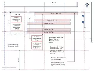
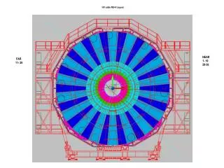
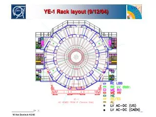
This document details the rack layout and configuration for the YE-1 system as of September 12, 2004. It outlines the capabilities of the top, middle, and lower floors of the rack, including slot allocation and channel counts for various RE components. The schematic includes connections between connector boxes and logical trigger strips, visualizing the layout in a "Bird's view". The arrangement facilitates the required electrical infrastructure for optimal performance of the RPCs on designated disks, ensuring precise operational functionality.

Rack Layout and Configuration for YE-1 System with Chamber Details
E N D
Presentation Transcript
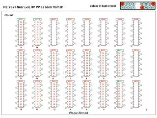
YE-1 +x top floor (9/12/04) 3*100A =12 slots for 3LBB 2*Dis12=24 ch for 6 RE1/2, 6 RE1/3 6 RE2/2, 6 RE2/3
YE-1 +x lower floor (9/12/04) 3*100A =12 slots for 3 LBB 2*100A = 8 slots for 3 LBB RE1/1 5*Dis12=60 ch for 12 RE1/2, 12 RE1/3 12 RE2/2, 12 RE2/3
YE-1 -x top floor (9/12/04) 3*100A =12 slots for 3 LBB 2*100A = 8 slots for 3 LBB RE1/1 18 RE1/1 (staged) 5*Dis12=60 ch for 12 RE1/2, 12 RE1/3 12 RE2/2, 12 RE2/3
YE-1 -x lower floor (9/12/04) 3*100A =12 slots for 3 LBB 2*Dis12=24 ch for 6 RE1/2, 6 RE1/3 6 RE2/2, 6 RE2/3 18 RE1/1 (staged)
strip 1 Connector Box A1 A2 B1 B2 Connector Box seen from top of chamber: A2 A1 B1 strip 1 C2 B2 C1 RPC Chamber C1 C2 Strip row B,C - strip 1 on pins 1,2 of conn. B1 (C1), strip 17 on on pins 1,2 of conn. B2 (C2), Strip row A - strip 1 on pins 31,32 of conn. A1, strip 17 on on pins 31,32 of conn. A2
Sector10/36 scheme1 scheme1 scheme2 Sector2/36 scheme2 Sector1/36 scheme1 scheme2 Sector36/36 RPC strip #1 Log strip #1 Log strips (logical trigger strips) counts clockwise looking along Z axis
Sector10/36 scheme1 Sector2/36 scheme1 scheme1 Sector1/36 scheme1 Sector36/36 RPC strip #1 Log strip #1 Log strips (logical trigger strips) counts clockwise looking along Z axis
RPC’s on disks “Bird’s view” REn/3 YE+3 YE+2 Phi=95 deg. Phi=85 deg. YE+1 z Scheme 1 IP x Scheme 2 RE1/3 YE-1 RE2/3 Scheme 1 YE-2 YE-3
RPC’s on disks “Bird’s view” REn/2 YE+3 YE+2 Phi=95 deg. Phi=85 deg. YE+1 z Scheme 1 Scheme 1 Scheme 2 IP x Scheme 1 Scheme 2 Scheme 2 RE1/2 YE-1 RE2/2 Scheme 1 Scheme 1 Scheme 1 YE-2 YE-3
RPC’s on disks “Bird’s view” RE1/1 YE+3 YE+2 Phi=95 deg. Phi=85 deg. YE+1 z IP x RE1/1 YE-1 YE-2 YE-3