Download
1 / 11
140 likes | 631 Vues
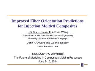
Improved Fiber Orientation Predictions for Injection Molded Composites. Charles L. Tucker III and Jin Wang Department of Mechanical and Industrial Engineering University of Illinois at Urbana-Champaign John F. O’Gara and Gabriel DeBarr Delphi Research Labs NSF/DOE/APC Workshop:

E N D
Improved Fiber Orientation Predictions for Injection Molded Composites Charles L. Tucker III and Jin Wang Department of Mechanical and Industrial Engineering University of Illinois at Urbana-Champaign John F. O’Gara and Gabriel DeBarr Delphi Research Labs NSF/DOE/APC Workshop: The Future of Modeling in Composites Molding Processes June 9-10, 2004
L z y x 2h Fiber Orientation Prediction: State of the Art • Describe orientation using A = pp • Orientation evolves according to Jeffery’s eqn. + interaction term • Hele-Shaw or 3-D mold filling simulation gives velocity distribution, D, W p
E11 E22 W L 2h The Problem: Orientation at Short Flow Lengths • Edge-gated strips, PBT 30% glass fiber • Measure elastic modulus in flow (E11) and crossflow (E22) directions • Predict modulus using measured or predicted fiber orientation
z z x x Orientation Structure: End-Gated Plaque top 2h shell: flow-aligned shell shell midplane core core: random or cross-flow (depending on inlet) bottom bottom midplane top
1.5, 2.0, 3.0, 6.0 mm A C B 80 mm 90 mm Predicted vs. Measured Orientation, Standard Model • In short plaques, predicted core is too narrow • Leads to over-prediction of E11,under-prediction of E22 • 2 mm, slow fill
Progress Toward a Better Model • Hypothesis: fibers experience local strain that is lower than average • resin-rich “slip layers” absorb most of the strain • fibers follow Jeffery-type motion based on local strain rate • Strain Reduction Factor (SRF) = (fiber strain rate / total strain rate)
Experiment vs. SRF Theory • New theory with SRF=20 does a good job for short plaquesover a range of thicknesses and filling speeds • 80902 mm • slow fill speed
Further Steps for an Improved Model • Our simple SRF theory is not objective • does not behave sensibly in rigid-body rotation;need an objective version of the model • Can only get SRF value by fitting experimental data • need a micromechanics theory to predict SRF if SRF = 20, fiber rotates at 5 RPM! flow rotates at 100 RPM
plate measur. measr. measur. simul. simul. simul. Long-Fiber/Thermoplastic Composites :Predicted vs. Measured Orientation Data from Reinhard Hafellner, Advanced Polymer Engineering Leoben, Austria specimen “plate”
Gaps: Processing of Injection Molded Composites • Fiber orientation modeling • capture the transient behavior at short flow lengths • models for long-fiber thermoplastics (include migration, fiber breakage, bundle dispersion) • predict orientation model parameters (CI, SRF) as function of fiber volume fraction, l/d, . . . • models tested in a variety of flow geometries • Fiber orientation measurement methods • non-destructive • capture full 3-D orientation • use online • . . .
Gaps, continued • Models for warp/shrink/residual stress • state of the art: predict warp within factor of 2 • reach quantitative accuracy (fiber orientation, matrix PVT, . . . ) • incorporate flow-induced crystallization of matrix