Download
1 / 58
640 likes | 935 Vues
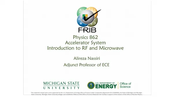
Physics 862 Accelerator System Introduction to RF and Microwave. Alireza Nassiri Adjunct Professor of ECE. Outline. Three lectures: Lecture 1 – today Introduction Overview of RF power generation Lecture 2 – Wednesday, November 7 Power transport – part one

E N D
Physics 862 AcceleratorSystem Introduction to RF and Microwave Alireza Nassiri Adjunct Professor ofECE
Outline • Threelectures: • Lecture 1 –today • Introduction • Overview of RF powergeneration • Lecture 2 – Wednesday, November7 • Power transport – partone • Lecture 3 – Wednesday, November7 • Power transport – parttwo • Introduction to low-level rf andcontrols • Homework 10 A.Nassiri
ElectromagneticSpectrum • All the electromagnetic waves travel with the same velocity (i.e. 3 X 10⁸ m/s) in the free space with different frequencies. The arrangement of electromagnetic radiations according to wavelength or the frequency is referred as electromagneticspectrum. • As we know electromagnetic spectrum has no definite upper or lower limit and various regions of EM spectrum do not have sharply definedboundaries. • The electromagnetic spectrum types, their frequency, wavelength, source and applications have been outlined in the table below. As mentioned EM waves include electric wave, radio wave, microwave, infrared, visible light,ultra violet,X-rays,gamma rays and cosmicrays. 10 A.Nassiri
ElectromagneticSpectrum 10 A.Nassiri
Introduction • RF transmitter for acceleratingcavities • Cavity tuningloop • Amplitudeloop • Phaseloop RF Distribution ControlSystem FourComponents RFSource Powersupply Transport (WG system) LLRF Power Pre- amp. MasterOscillator LLRF Amplifier • PowerSupply • Modulator TerminationLoad RFsource AcceleratingCavity What is the OverallEfficiency? Later in thelecture. 10 A.Nassiri
Glossary of Terms as relates toRF • Frequencyrange • Klystrons are dominant and used above 300MHz • Other devices such as IOT, Diacrode, Tetrode and SSA below 300MHz • Peakpower • Is related to energy gain in an accelerator as well as the overall length of a given accelerator system. High peak power typically results in arcing within the acceleratingstructures. • Averagepower • Is defined as the product of peak power and DF in pulsedsystems • For CW systems, the output power is equal to the averagepower. • Define the amount of heat produced by thesystem • Gain • Defines by rf drive. Klystrons, in general, have a high gain ~50 dB ( i.e. less drive power). IOTs are low gain devices- ~20 dB ( i.e., more drivepower). • PhaseStability • Klystron is a voltage driven device and the rf phase is stable if the voltage isstable. 10 A.Nassiri
Glossary of Terms as relates toRF • Decibel (dB) • o𝑑𝐵𝑚=10 𝐿𝑜𝑔10 ("PmW") • o𝑑𝐵=10 𝐿𝑜𝑔10 (𝑃1/𝑃2) • o𝑑𝐵=20 𝐿𝑜𝑔10 (𝑉1/𝑉2) • o𝑑𝐵𝑉=20 𝐿𝑜𝑔10 ("VVrms") • o𝑑𝐵µ𝑉=20 𝐿𝑜𝑔10 (𝑉µ𝑉𝑟𝑚𝑠) • o𝑑𝐵𝑐=10 𝐿𝑜𝑔10 (𝑃𝑐𝑎𝑟𝑟𝑖𝑒𝑟/𝑃𝑠𝑖𝑔𝑛𝑎𝑙) • dBm,W (𝑥𝑑𝐵𝑚/10) 𝑃 =10 𝑥 =10𝐿𝑜𝑔 P 𝑑𝐵𝑚 10 mW 𝑚𝑊 10 A.Nassiri
Glossary of Terms as relates toRF —𝑃∕𝑃𝑟𝑒𝑓=10(𝑥/10) 𝑑𝐵 𝑥𝑑𝐵=10 𝐿𝑜𝑔10(𝑃/𝑃𝑟𝑒𝑓) 10 A.Nassiri
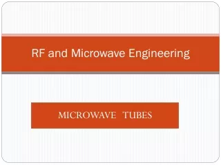
RF PowerSources • Two principal classes of microwave vacuum devices are in common usetoday: • o Linear-beamtubes oCrossed-field tubes Linear BeamDevices Klystrons Hybrid O-typeTWT Twystron Helix Ring-bar TWT Helix BWO Two -cavity Multi-cavity Coupled cavity TWT Laddertron Reflex 10 A.Nassiri
Linear BeamDevices • In a linear-beam tube, as the name implies, the electron beam and the circuit elements with which it interacts are arrangedlinearly. • In such a device, a voltage applied to an anode accelerates electrons drawn from a cathode, creating a beam of kineticenergy. • Power supply potential energy is converted to kinetic energy in the electron beam as it travels to- ward the microwavecircuit. • A portion of this kinetic energy is transferred to micro-wave energy as RF waves slow down the electrons. The remaining beam energy is either dissipated as heat or returned to the power supply at thecollector. • Because electrons will repel one another, there usually is an applied magnetic focusing field to maintain the beam during the interactionprocess. 10 A.Nassiri
Cross-FieldDevices • The magnetron is the pioneering device of the family of crossed-fieldtubes. • Although the physical appearance differs from that of linear-beam tubes, which are usually circular in format, the major difference is in the interaction physics that requires a magnetic field at right angles to the applied electricfield. • Whereas the linear-beam tube sometimes requires a magnetic field to maintain the beam, the crossed-field tube always requires a magnetic focusingfield. • Crossed-fielddevices Distributedemission Injected beamtube MBWO Carcinotron Magnetron Crossed-fieldamplifier Voltage tunable magnetron Crossed fieldamplifier 10 A.Nassiri
Commercial RFSources Tetrodes & Diacrodes available from industry 10000 peak <1 Power kW per singletube ms 1000 100 10 0 100 200300 Frequency MHz 400 500 12 A.Nassiri PHY 862 AcceleratorSystems
AmplifierClass ClassA Operativecurve ClassB ClassC Operativecurve Operativecurve Output Signal OutputSignal Less than180⁰ Output Signal Unsused area Unsused area Input Signal Input Signal Input Signal Efficiency 100% 75% 50% 25% 0% C B B 180⁰ πCo AB A A AB C 270⁰ 3π/4 0⁰ nductionAngle0 90⁰ 360⁰ 2π 13 A.Nassiri PHY 862 AcceleratorSystems
Grid VacuumTubes • The physical construction of a vacuum tube causes the output power and available gain to decrease with increasing frequency. The principal limitations faced by grid-based devices include the following: • Physical size. Ideally, the RF voltages between electrodes should be uniform, but this condition cannot be realized unless the major electrode dimensions are significantly less than 1/4 wavelength at the operating frequency. This restriction presents no problems at VHF, but as the operating frequency increases into the microwave range, severe restrictions are placed on the physical size of individual tubeelements. • Electron transit time. Inter electrode spacing, principally between the grid and the cathode, must be scaled inversely with frequency to avoid problems associated with electron transit time. Possible adverse conditions include: 1) excessive loading of the drive source, 2) reduction in power gain, 3) back-heating of the cathode as a result of electron bombardment, and 4) reduced conversionefficiency. • Voltage standoff. High-power tubes operate at high voltages. This presents significant problems for microwave vacuum tubes. For example, at 1 GHz the grid-cathode spacing must not exceed a few mils. This places restrictions on the operating voltages that may be applied to the individualelements. • Circulating currents. Substantial RF currents may develop as a result of the inherent inter electrode capacitances and stray inductances/capacitances of the device. Significant heating of the grid, connecting leads, and vacuum seals mayresult. • Heat dissipation. Because the elements of a microwave grid tube must be kept small, power dissipation is limited. 16 A.Nassiri
Tetrode • Vacuum tube based on intensity modulation of a electronbeam • Typicalparameters: • Frequency: accelerator applications up 300 to400MHz • Finite electron drift time limits the achievable gain at higherfrequencies • Limiter gain of ~15 dB mean that thigh power tetrode amplifiers need 2-3 stage of amplification, which drives up the cost andresults in complicated amplifiersystems. GroundedGrid GroundedCathode 16 A.Nassiri
PlanarTriode • The envelope is made of ceramic, with metal members penetrating the ceramic to provide for connection points. The metal members are shaped either as disks or as disks with cylindricalprojections. • The cathode is typically oxide-coated and indirectly heated. The key design objective for a cathode is high emission density and long tube life. Low-temperature emitters are preferred because high cathode temperatures typically result in more evaporation and shorterlife. • The grid of the planar triode is perhaps the greatest design challenge for tube manufacturers. Close spacing of small-sized elements is needed, at tight tolerances. Good thermal stability also is required, because the grid is subjected to heating from currents in the element itself, plus heating from the cathode and bombardment of electrons from thecathode. • The anode, usually made of copper, conducts the heat of electron bombardment to an external heat sink. Most planar triodes are air- cooled. • Planar triodes designed for operation at 1 GHz and above are used in a variety of circuits. The grounded-grid configuration is most common. The plate resonant circuit is cavity-based, using waveguide, coaxial line, or stripline. Electrically, the operation of the planar triode is much more complicated at microwave frequencies than at lowfrequencies. 16 A.Nassiri
Diacrode • The Diacrode (Thales) is a promising adaptation of the high-power UHF tetrode. The operating principle of the Diacrode is basically the same as that of the tetrode. The anode current is modulated by an RF drive voltage applied between the cathode and the power grid. The main difference is in the position of the active zones of the tube in the resonant coaxial circuits, resulting in improved reactive current distribution in the electrodes of thedevice. • Themaindifferenceisinthepositionof Double the output power at a given frequency the active resonant zonesofthetubesinthe coaxial circuits, resulting in improvedreactivecurrentdistributingin the tube’selectrodes. Double the frequency at givenoutput power. The tetrode is located at the end of 1/4, theoretically at the current nodeside. The Diacrode is located at the middle of the 1/2and thus the currentnodeandthevoltageanti-nodearesituatedatthecenter of the cathode/control grid and screen grid/anodespace. 17 A.Nassiri
IOT • Inductive Output Tube (IOT)Klystrode • IOT developed for accelerators [Thales, CPI]:80 kW CW at 470 –760MHz • High efficiency (70%) operation in classB • Intrinsic low gain ( 20– 25 dB) ⇒Pin= 1Kw • Less gain than klystrons but higher thantetrodes • No need for a long drift space ( likeklystrons) • More compact and costefficient • IOTs ( and all gridded tubes) are limited in their frequency reach by the distance of the control grid from thecathode. • The RF period has to be smaller than the time of flight from cathode to thisgrid. • Frequency of IOTs is limited to ~ 1.3GHz • The max. power of a single beam IOTs is limited to ~100kW. • Less Amplitude/Phase sensitivity to HVripples • Compact, external cavity ⇒easy tohandle • Low unit power ⇒powercombiners • 1.3 GHz for cw XFEL linacs andERLs • o 16 to 20 kW CW, efficiency 55 to 65% ( CPI,E2V, Thales) As atetrode As aklystron CERN SPS TH795 IOT transmitters. Two transmitters (4 tubes) deliver18 A.Nassiri PHY 862 AcceleratorSystems 480 kW at 801MHz.
MB-IOT • ESS doing R&D on Multi-Beam IOT • Alternative toklystrons • Twoprototypes • 1.3 MW @704 MHz up to 3.5 mspulse A.Nassiri
Klystron • Principle of klystrons was published by Oskar and Agnessa Heil (Germany) in1935. • During the same time, W. W. Hansen at Stanford was investigating “ a scheme for producing high- voltage electrons” for use in X-ray spectroscopy. In the process, he invented the microwave cavity , “Rhumbatron.” • Working with Hansen Varian brothers (Russell and Sigurd) developedklystron Beam arrivesat 1stcavity Beam arrives at 2nd cavity Electron gun Continuous beam Bunched beam Collector A.Nassiri
RF andMicrowave • Both RF and Microwave are used to represent frequency ranges in the electromagnetic spectrum. Both are used for many similar as well as different applications. RF is the short form for 'Radio Frequency'signal. • RF (RadioFrequency) • EM spectrum has been classified into eight regions based on radiation intensity. The major divisions are into radio spectrum and optical spectrum. Radio spectrum covers radio waves, microwaves andterahertz radiations. Optical spectrum covers infrared, visible, ultra violet, X-rays and gamma radiations. Radio waves range from 3 KHz to 300 GHz. Hence RF. starts from much lower than the microwave startingrange. • In radio waves antenna wavelength varies from hundreds of meters to about 1millimeter. • Microwave • The term "micro" means very small. It is basically millionth part of a unit. The term Microwave is used to identify EM waves above 1GHz in frequency because of short physical wavelength of these frequencies. Microwaves are basically radio frequency(RF) waves. However there is difference between RF and microwave as far as operating range and applications are concerned. Microwaves range starts from 300MHz to300GHz. • Most of the microwave applications range up to 100 GHz. Following are the unique features of themicrowaves: • High antenna gain anddirectivity • Large Bandwidth • It travels by LOS(Line OfSight) • In 1-10GHz range Microwaves noise level is very low and hence very low signal can also be easily detected atreceiver • Microwaves penetrate ionosphere with less attenuation as well as lessdistortion. A.Nassiri
Difference between RF andMicrowave • The terms RF and Microwave are interchangeably used by engineers across the globe, there is slight distinction between them. The same have been highlighted in thepage. • Although there is ambiguity in starting range of microwave, in general it starts from 1GHz and span till 1 Tera-Hertz. Hence corresponding wavelengths range from 30cm to0.3mm. A.Nassiri
Properties ofMicrowaves Microwave is an electromagnetic radiation of shortwavelength. They can reflect by conducting surfaces just like optical waves since they travel in straightline. Microwave currents flow through a thin outer layer of an ordinarycable. Microwaves are easily attenuated within shortdistances. They are not reflected byionosphere A.Nassiri
Advantages andLimitations • Increased bandwidthavailability • Microwaves have large bandwidths compared to the common bands like short waves (SW), ultrahigh frequency (UHF) waves,etc. • For example, the microwaves extending from = 1 cm - = 10 cm (i.e) from 30,000 MHz – 3000MHz, • this region has a bandwidth of 27,000MHz. • Improved directiveproperties • The second advantage of microwaves is their ability to use high gaindirectiveantennas, any EM wavecan be focused in a specified direction (Just as the focusing of light rays with lenses orreflectors) • Fading effect andreliability • Fading effect due to the variation in the transmission medium is more effective at lowfrequency. • Due to the Line of Sight (LOS) propagation and high frequencies, there is less fading effect and hence microwave communication is morereliable. • Power requirements • Transmitter / receiver power requirements are pretty low at microwave frequencies compared to that at short waveband. A.Nassiri
Advantages andLimitations • Transparencyproperty • Microwave frequency band ranging from 300 MHz – 10 GHz are capable of freely propagating through the atmosphere. • The presence of such a transparent window in a microwave band facilitates the study ofmicrowave • radiation from the sun and stars in radio astronomical research ofspace. • Applications • Scientific –Accelerators • Telecommunication: Intercontinental Telephone and TV, space communication (Earth – to – space and space – to – Earth), telemetry communication link for railwaysetc. • Radars: detect aircraft, track / guide supersonic missiles, observe and track weather patterns, air traffic control (ATC), burglar alarms, garage door openers, police speed detectorsetc. A.Nassiri
Applications • Scientific –Accelerators • Telecommunication: Intercontinental Telephone and TV, space communication (Earth – to – space and space – to – Earth), telemetry communication link for railwaysetc. • Radars: detect aircraft, track / guide supersonic missiles, observe and trackweather • patterns, air traffic control (ATC), burglar alarms, garage door openers, police speed detectors etc. • Commercial andindustrial • oMicrowave oven oDrying machines – textile, food and paper industry for drying clothes, potato chips, printed matters etc. oFood process industry – Precooling / cooking, pasteurization / sterility, hat frozen / refrigerated precooled meats, roasting of food grains /beans. oRubber industry / plastics / chemical / forest product industries oMining / public works, breaking rocks, tunnel boring, drying / breaking up concrete, breaking up coal seams, curing ofcement. oDrying inks / drying textiles, drying / sterilizing grains, drying / sterilizing pharmaceuticals, leather, tobacco, powertransmission. o Biomedical Applications ( diagnostic / therapeutic ) – diathermy for localized superficial heating,deep electromagnetic heating for treatment of cancer, hyperthermia ( local, regional or whole body for cancertherapy). A.Nassiri
Performance Parameters of Different RFSources F. Gerigk, CERN,IPAC2018 A.Nassiri
RF Sources EfficiencySummary Courtesy of E. Montesinos,CERN A.Nassiri
PRFin ≃ 1 to 5 % PRFout (Gain is usually high) ηRF/DC ≃ 65 % (includingoverhead) η PAC/PDC ≃ 95 % to 98% Amplifier cooler ≃ 15 % PRFout Building cooler ≃ 30 %PRFout 𝐎𝐯𝐞𝐫𝐚𝐥𝐥𝐞𝐟𝐟𝐢𝐜𝐢𝐞𝐧𝐜𝐲 Overall Efficiency of RFSystem Amplifier Cooler Building Cooler Heatout 𝐏𝐑𝐅𝐨𝐮𝐭 = RF powerin 𝐏𝐑𝐅𝐢𝐧 + 𝐏 𝐀𝐂𝐢𝐧 + 𝐏𝐜𝐨𝐨𝐥𝐞𝐫𝐬 RF powerout DUT (Device UnderTest) Amp 𝐏 ≃𝐑𝐅𝐨𝐮𝐭 𝐏𝑹𝑭𝒐𝒖𝒕 (𝟎. 𝟎𝟓 + 𝟏. 𝟔𝟐 + 𝟎.𝟒𝟓) DC powerin AC powerin ≃ 𝟒𝟓% AC/DC 𝑶𝒗𝒆𝒓𝒂𝒍𝒍𝒆𝒇𝒇𝒊𝒄𝒊𝒆𝒏𝒄𝒚 𝑷𝑹𝑭𝒐𝒖𝒕 ≃ ≃ 45% 𝑷𝑨𝑪𝒊𝒏+𝑷𝑹𝑭𝒊𝒏+𝑷𝒄𝒐𝒐𝒍𝒆𝒓𝒔 A.Nassiri
RF Power Distribution • Consider a simple high power rflayout: Circulator RF powersource Klystron,etc. DUT(Cavity) Driver Amplifier Coaxialline Waveguide Waveguide Load(Termination) CoaxialLines Coaxial cables are often with PTFE foam to keepconcentricity 𝐷 𝑑 Flexible lines have spacer helicoidally placed all along theline 60 Rigid lines are madeof two rigid tubes maintained concentric withsupports Zc=ε ln 𝑟 30 A.Nassiri PHY 862 AcceleratorSystems
RectangularWaveguide • Waveguides are usable over certain frequencyranges • For very lower frequencies the waveguide dimensions become impracticallylarge • For very high frequencies the dimensions become impractically small & the manufacturing tolerance becomes a significant portion of the waveguidesize λ λ𝑔= Wavelength 1−( λ)2 2𝑎 Cut-off frequency dominant mode Cut-off frequency next higher mode Usable frequencyrange c 2𝑎 c 4𝑎 f= c b a f c2= 1.3 fc to 0.9fc2 37 A.Nassiri
Reflection • Reflection occurs when there is impedance mismatch between the device under test ( e.g., cavity) and theline. • SWR is a measure of this impedance mismatch where a incident wave is partially reflected when the TL in not terminated in resistance equal to its characteristicimpedance • The reflection coefficient, is definedas Source Zc Г =𝑉𝑟 Line =Z c 𝑉𝑓 • Boundaryconditions: • = -1 short circuit , full negativereflection • = 0 perfectly matched, noreflection • = 1 open circuit, full positivereflection V Vf r Zd Zc Zd 37 A.Nassiri
Reflection • Forward and reflected waves are inphase = 𝑉𝑓 + 𝑉𝑟 = 𝑉𝑓 + Г𝑉𝑓 =1+Г𝑉𝑓 𝑉𝑚𝑎𝑥 Zc Source Line =Zc Fullreflection:𝑉𝑚𝑎𝑥 =2𝑉𝑓 • When the wavesare180out ofphase = 𝑉𝑓 − 𝑉𝑟 =𝑉𝑓−Г𝑉𝑓 = 𝑉𝑚𝑖𝑛 1−Г𝑉𝑓 Fullreflection: 𝑉𝑚𝑎𝑥 =0 Vf Vr 𝑉𝑚𝑎𝑥1+Г = 1−Г V𝑆𝑊𝑅= Zd 𝑉𝑚𝑖𝑛 37 A.Nassiri
Reflection • Incaseof a full reflection Vmax = 2Vf • (Pmax equivalent to 4Pf) • One needs to protect the RF power amplifiers if Pr >Prmax • o Not always possible or may not be desirable since it may impactoperation Pf P r Swift protection ifPr 37 A.Nassiri
Circulator • Protect from this reflectedpower • o passive non-reciprocalthree-port device • osignal entering any port is transmitted only to the next port in rotation • The best place to insert it is close to the reflectionsource • Lines between circulator and DUT will see 4xPf if fullyreflected. • A load for Pf is needed on port 3 to absorbPr • Vf Vf Vr Vr Load 37 A.Nassiri
Circulator • Even in case of full reflection Vmax = 2Vf (Pmax equivalent to 4Pf) • RF power amplifiers will not see reflected power and will not beaffected • Lines between circulator and DUT MUST at least be designed for 4Pf • Loads must be designed forPf 4Pf P f Pf Load 37 A.Nassiri
Limitations of MicrowaveTubes • Performance is limited by a number of factorsincluding: • Heatdissipation • Voltagebreakdown • Output window failure • Multipactor discharge • The RF structures and the windows of microwave tubes generally scale inversely withfrequency. • The maximum CW or average power that can be handled by a particular type of tube depends upon the maximum temperature that the internal surfaces can be allowed toreach. • This temperature is independent of the frequency, so the power that can be dissipated varies inversely with thefrequency. • Gyrotrons can handle a higher power of the same frequency than klystrons because they have simpler structures and, if operated in a higher order mode, their structures are larger for a given frequency. • The power is also limited by the power that can be generated by an electron gun and formed into a beam. The beam diameter scales inversely with frequency and the beam current density is determined by the maximum attainable magnetic focusingfield. • Since the field is independent of frequency the beam current scales inversely with the square of the frequency 37 A.Nassiri
Limitations of MicrowaveTubes 𝑰ൗ𝑽𝟏.𝟓 • The beam voltage is related to the current by the gunperveance • range of 1.0 to 2.0 for powertubes. which typically inthe • The maximum gun voltage is limited by the breakdown field in the gun and therefore varies inversely with frequency for constantperveance. • The maximum power obtainable from a tube is 𝑓−2.5 𝑡𝑜 −3.0 depending on the assumptionsmade. • The efficiencies of tubes tend to fall with increasing frequency. This is partly because the RF losses increase with frequency and partly because of the design compromises that must be made at higher frequencies. • The maximum power obtainable from a pulsed tube is often determined by the power-handling capability of the output window. The output window of an external cavity klystron is in the form of a cylinder within the cavity and close to the output gap. This arrangement is limited to powers of about 70 kW. At higher power levels integral cavities are used and the power is brought out through waveguide or coaxial linewindows. • Very high power klystrons commonly have two windows in parallel to handle the full outputpower. • Windows can be destroyed by excessive reflected power, by arcs in the output waveguide, by X-ray bombardment, and by the multipactor discharges described in the next Section. The basic cause of failure is overheating and it is usual to monitor the window temperature and to provide reverse power and waveguide and cavity arcdetectors. A.Nassiri
Power Handling – CoaxialLine • The coaxial transmission line supports a TEM mode which has no cut-off frequency, that is, coax can be used down to d.c. This mode, in which the electric field is radial and the magnetic field azimuthal, has phase velocity and characteristic impedance givenby • Coaxial transmission lines for high-power transmission are commonly available in 50 and 75 characteristic impedances, the former representing a compromise between breakdown field strength and power handling capacity, and the latter being selected for minimum attenuation. The ratio b/a is fixed by the characteristic impedance of the line at 2.3 for the 50 lineand • 3.49 for the 75 line. Propagation on a coaxial line is as exp j(t −z)where • = +j • The loss parameter is givenby • a • b A.Nassiri
Power Handling – CoaxialLine • The average power carried on a coaxial line depends on the peak electricfield • As a reference, the breakdown electric field strength in dry air at standard pressure and temperature is 3 MV/m. • Higher-order modes (TE and TM modes) can propagate in coax at higher frequencies, and one wants to avoid these modes because mode conversion from TEM to TE or TM modes represents a source of power loss. The cut off wavenumber for the mode with the lowest cut off frequency, the TE11 mode, is approximately givenby A.Nassiri
Coaxial Line – A numericalExample • Let us consider a 500 MHz power system using a rigid, air-filled, 75 aluminum 14 inch outer diameter outer conductor transmission line. The radii of the outer and inner conductors are then a = 51 mm and b = 178 mm. Neglecting higher order waveguide mode effects and cu= 5.8× 10⁷ mhos/m and Al= 3.5 × 10⁷ mhos/m, so that the surface resistancesare𝑅𝑎= −1=5.8 × 10⁻³ per squareand 𝜎𝑐𝑢𝛿𝑐𝑢 𝑅𝑏= −1=7.5 × 10⁻³ per square. The attenuation constantis: 𝜎𝐴𝐿𝛿𝐴𝐿 • The power handling capacity ( w/o any corrections)is • The cut-off wavenumberis: A.Nassiri
Coaxial Line – A numericalExample • Thus we would not want to use this particular coaxial line much above 400 MHz, for example. Raising the TE11 cut-off frequency to 550 MHz for the same characteristic impedance would require a = 41 mm and b=142 mm willyield • and a maximum average power of 155MW. A.Nassiri
Standard WaveguideCharacteristics A.Nassiri
Standard WaveguideCharacteristics Attenuation constant for a 14 inch coaxial line and WR1800WG. A.Nassiri
Standard WaveguideCharacteristics Attenuation constant vs frequency for standardWGs. A.Nassiri
RectangularWaveguide • Standard rectangular waveguides have aspect ratios close to 2:1, but reduced-height waveguides are sometimes used for special purposes. The propagation constant in rectangular waveguide is givenby where the cut-off wavenumber kc = /a and the cut-off frequency fc = c/2a for the lowest mode of propagation. In this mode, the TE10 (or H10) mode, the electric field is normal to the broad wall and the magnetic field is parallel to the broad wall. Assuming that b = a/2 the attenuation constant is found tobe and the maximum power is A.Nassiri
RectangularWaveguide • Higher order waveguide modes are also a consideration in using rectangular waveguides. For the conventional choice of a 2 : 1 aspect ratio in the transverse dimensions, the first higher order mode is the TE20 mode (H20 mode), for which the cut-off frequency is just twice the cut-off frequency of the dominant TE10 mode (H10 mode). Common practice is to use a rectangular waveguide witha • ±20% bandwidth about a center frequency which is 1.5 times the waveguide cut-off frequency. Roughly put, one operates in a band from approximately 1.25 fc to 1.90fc. • In 200 MHz – 400 MHz, where one might want to choose either coaxial transmission line for its more compact size, or a waveguide for its lower attenuation, one must bear in mind both attenuation and power-handlingcapacity. • Consider the high-power transmission system before for a WR1800 WG made of Al with a =18 • inches, the attenuation constantis: Max. poweris A.Nassiri
RectangularWaveguide • So operating at 500 MHz, choosing a waveguide over a coax isobvious. • In order to avoid higher order waveguide mode losses, the diameter of the coax must be reduced, leading to higher attenuation and lower power-handling capacity as shown above. For short distances of transmission, however, the higher losses of coaxial transmission lines may beacceptable. A.Nassiri
Derivation of attenuation constant in coaxialline • For a coaxial line with inner radius a and outer conductor radius b, the electric and magnetic fields of the dominant TEM mode are givenby where 0 is the characteristic impedance of free space. Corresponding to these field quantities one can calculate the integrated quantities of voltage andcurrent and where the voltage and the current on the inner conductor are positive for positiveE A.Nassiri
Derivation of attenuation constant in coaxialline • Ration of V/I gives characteristic impedance of the coaxialline • Poynting vector for this modeis • Integrating over the cross sectional area of the line yields powerflow: A.Nassiri