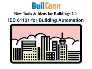
IEC 61131-3 Hands on Training
900 likes | 1.37k Vues
IEC 61131-3 Hands on Training. Evolution of Control Technology. PLC. PC Based Ctrls. 1950 s 1960 s 1970 s 1980 s 1990 s 2000 20011. Relays. The Future of Automation. Current. Future. FALCON. Simpler, more cost effective Single source supplier

IEC 61131-3 Hands on Training
E N D
Presentation Transcript
Evolution of Control Technology PLC PC Based Ctrls 1950s 1960s 1970s 1980s 1990s 2000 20011 Relays
The Future of Automation Current Future FALCON • Simpler, more cost effective • Single source supplier • Single software package (4 vs. 1) • Decreased maintenance costs • Lower installation costs
System Architecture Ethernet Production control
Graphical User Interface Editor Configuration Utility Visual BASIC I/O Drivers Graphical User Interface Communication Drivers HMI I/O Driver Tool Kit Symbol Server Toolkit Software Architecture Program Editor Logic Engine D L L D L L Open XP Environment
Program Editors • IEC 1131-3 Language Support • Ladder Diagram, Sequential Function Chart, Structured Text, Instruction List • Windows based Editing Tools • Familiar Tool Bars, Displays & Key Commands • On-line Help throughout • On-line and Off-line Editing • Simulate program without actual I/O Easy Program Editing
FALCON Workshop • IEC-1131 Overview • International Standard of the International Electrotechnical • Commission (Global programming standard). • Specifies the syntax and semantics of a unified suite of • programming languages for programmable controllers • (IEC-61131-3). • Graphical Languages • Ladder Diagram (LD) • Function Block Diagram (FBD) • Sequential Function Chart (SFC) • Textual Languages • Instruction List (IL) • Structured Text (ST)
Diagnostic Tools • On-line editing and debugging. • “Watch Window” allows display and forcing of variables and view of actual program status. • On-line Help Menu with contents and search capability. • Application specific message boxes driven by program. • System event logging. • I/O Status bits Increases Productivity
I/O &Communication Drivers • I/O • Popular network • Cost effective IO solution • Supports up to six interfaces simultaneously • Motion Control • See brochure for complete list Ethernet Communication to 6 networks at the same time
Profibus DP DeviceNet EtherNet I/P Interbus-S CAN-Open SERCOS Modbus RTU Modbus TCP/IP SIRPLEX AS-I AB RIO AB DH, DH+ I/O &Communication Drivers • GE 90/30 • GE Genius • Beckhoff TCP/IP • Yaskawa Remote I/O • Opto-22 Parallel • OptoMux • COM 1-4 Serial Channels • Wonderware • GE Cimplicity • Intellution FixDMAX • Visual Basic 6.0, .Net • CMC PCI I/O Interface Partial List of Device Drivers
Real Time Motion Control • The FALCON provides motion connectivity to the popular motion experts -Standard Motion Control Algorithms -Flexible to meet the users needs -Cost effective IO solution -RTE providing Real Time Control Communication to 6 networks at the same time
Complete Development Sys. Programming in SFC, Ladder Diagram and Structured Text Graphical User Interface Runtime Engine unlimited number of I/O
Logic Engine • Runtime Logic Engine • unlimited I/O points (digital or analog) • with or without FALCON GUI. • Executes LD, SFC+ and ST programs • Monitoring and change of data values (but not editing) Logic Engine • Includes Drivers for: • Modbus TCP/IP
User Interfaces / Toolkits • HMI (third party) • High-End User Interface/Distributed Structure /Historical capabilities • Full Featured HMI offering • FALCON Graphic User Interface • Embedded Graphical User Interface (GUI) • Easy to implement • Low cost HMI • Common database • High performance • Toolkits • Function Block Toolkit • Visual Basic Toolkit: License free applications
Product Family • FALCON Software Only • FALCON Loaded on 15’’ Color Touch (3 PCI) • Pro Series (Enclosed Box with IO) • Service (PC Selection 10 or 15, Loading and Configuration, Telephone Support)
Key Points • Real-time Control with Integrated HMI, I/O, OI, Motion and Diagnostics • One-Stop Shopping of Products and Services Open software environment on PC Platforms on XP • IEC 61131-3 Standard • Scaleable PC Environment • HMI Choices- Low-end HMI, HMI, Visual BASIC • Programmable Machine Diagnostics • Reduced hardware, engineering and total life cycle cost
System Overview Hardware Structure FALCON is built upon a standard PC hardware platform. The main CPU provides both the application programming environment and application program execution (run time).
Hardware Architecture • Mix different manufacturers process & motion control • FALCON runs under Windows XP as a protected user application • Drivers for each type of I/O are provided • Use standard PLC I/O • No PLC needed PLC
System Overview Software Subsystem Program Editor/ Debugger Operator Interface Configuration Utility Program Manager Program Execution I/O Scanner
Starting FALCON Starting the Program Editor • Access Levels: • Five Levels : 0-4 • “4567” default for level 4 • Level 0: Activate operator screens and controls in the GUI. • Selecting and running SFC programs. • Level 1: Running/Aborting RLL programs, viewing RLL/ • SFC programs. • Level 2: Editing SFC programs and executing project • management functions • Level 3: Editing RLL, modifying GUI, and modifying system • configuration files. • Level 4: Changing the passwords for access levels 1 - 4.
Working with Projects About Projects: Project Management allows the user to organize the Work into logical divisions called projects: Program files Configuration files Operator Interface files
Controlling I/O with FALCON Configuration Utility Overview The configuration files tell FALCON what interface cards are in the computer, and what I/O are attached to those cards. System Slot Board Profibus DeviceNet Connector Port I/O Point
Create New System Configuration • Hands On Exercise • Page 10- 12
Multitasking – I/O Scan Rate PLC Overhead I/O Scan Logic Outputs Limited capacity
Multitasking – I/O Scan Rate I/O Scan Rate I/O Logic Other App’s FALCON Runtime HMI, Network or ? PC Allow enough time to solve logic and service the other applications. Expandable capacity
Sequential Function Chart (SFC) SFC Overview Editor • Steps • Macro Steps • Actions • Transitions • Jump Labels • Jumps • Loops • Select Diverge • Simultaneous Diverge • Application Icon • Add Comments • Structured text in Steps • Step variables • Boolean or LD Transitions • Scaleable display • On-line changes
SFC- Example Transition 1 Transition 3 Transition 2 Step 2 Step 3 Step 4 Transition 4 Transition 5 Transition 3 Transition 2 Step 3 Step 4 Selective Divergence Selective Convergence Transition 1 Step 2 Transition 3 Transition 2 Transition 3 Step 3 Step 4 Step 3 Step 4 Transition 4 Simultaneous Divergence Simultaneous Convergence Common Sequences
Step System Variables Step_is_active(X) – STEP1.X - X = TRUE when active Step time(T) - STEP1.T - T = Elapsed time of step milliseconds T set to Zero at step start
Creating an SFC • Hands On Exercise • Page 17
Symbols/Data Types Symbol Mgr Overview The Symbol Manager allows the user to create and manage symbols for use in RLL or SFC programs.
Symbols and Data Types Symbol Data Types • TIME • Timer (TMR) • User-Defined Data Type • PID Data Type • PID Inputs and Outputs • PRGCB Data Type • Pre-Defined System Symbols • REAL • Integer (INT) • Double WORD (DWORD) • WORD • BYTE • Boolean (BOOL) • DATE • Time of Day (TOD) • STRING
Symbol Manager ? • Symbol Types: • Local – Used in program where defined only. • Global – Available to all programs in project. • Operator Interface and DDE • External – I/O Points
Symbol Data Types MSB 0 LSB 7 • BOOL - Boolean (TRUE=1, FALSE=0) • BYTE – Unsigned integer 8 bit • Range 0 to 255 • DATE – D#YYYY-MM-DD • YYYY = 1970 to 9999 • MM = 1 to 12 • DD = 1 to 31 • TODAY = Current date
Symbol Data Types • DWORD - Unsigned integer 32 bit • Range 0 to 4294967296 • INT – Integer • 32 bit word • Range –2146483648 to +2147483647 • REAL – Decimal • 64 bit word • Range +1.401298 E-48 to +3.402823 E38 LSB 31 MSB 0C
Symbol Data Types • String – ASCII characters • ASCII characters within “This is a valid string” • Hex - $41 $42 $43 = A B C • TIME – T# • D or d – Days T#1D2h: 1 day and 2 hours • H or h – Hours t#26H: 26 hours • M or m – Minutes t#5m45s: 5 minutes and 45 seconds • S or s – Seconds t#26s200MS: 26 Seconds and 200 milliseconds • MS or ms – Milliseconds T#900ms: 900 milliseconds
Symbol Data Types • TMR – Timer • Timer_name.PT = Real data value in seconds or T# format • Timer_name.EN = Boolean, will stop/start TMR • Timer_name.ET = elapsed time in seconds of TMR • Timer operations • Timer_name.EN = sets .ET to zero when TMR starts • Timer_name.ET = when equal to preset then Timer_name.EN is reset • Timer_name.EN = set to false then Timer_name.ET is frozen at the last value • Timer_name.ET = may be read any time
Symbol Data Types • TOD – Time of Day • TOD#HH:MM:SS • HH = 0 to 23 • MM = 0 to 59 • SS = 0 to 59 • NOW – Current system time • MOVE to define NOW • ADD to add a duration to NOW
Symbol Data Types LSB 15 MSB 0 • UINT/WORD • 16 bit unsigned integer • Range – 0 to 65535 • User-Defined Data Types • Groups of data types • Integers, Boolean, Strings…
Symbol Data Types • System Created Symbols • TODAY, NOW, NULL, TMR • Counters - RLL counters status – CTU, CTD, CTUD (Local) • Timers – RLL timer status – TOF, TON, TP (Local) • “stepname”.X - SFC STEP Active/inactive status (Local) • “stepname”.T – SFC STEP elapsed execution time (Local) • Motion Control – Status of axis, axis variable group, Program control and spindle • File Control – Status of file operations • Program Control – Status of PRGCB data types
Symbol Data Types • Run-Time Symbols • RT_ERROR – (INT) Math error • 0 = No error • 1 = divide by zero • 2 = negative square root • RT_ERROR must be cleared by the user • RT_FIRST_SCAN – (BOOL) • Set to true on first scan of first program to run • RT_SCAN_OVERRUN – (BOOL) • I/O scan + logic scan exceeds scan rate • RT_MAX_SCAN – (REAL) • Duration in ms of maximum scan duration
Symbol Data Types • Run-Time Symbols • RT_LAST_SCAN – (REAL) • Duration in ms of last scan duration • RT_AVG_SCAN – (REAL) • Duration in ms of average scan duration • RT_LOGIC_MAX – (REAL) • Duration in ms of maximum logic scan duration • RT_LOGIC_LAST – (REAL) • Duration in ms of last logic scan duration • RT_LOGIC_AVG – (REAL) • Duration in ms of average logic scan duration
Symbol Data Types • Run-Time Symbols • RT_IO_MAX – (REAL) • Duration in ms of maximum I/O scan duration • RT_IO_LAST – (REAL) • Duration in ms of last I/O scan duration • RT_IO_AVG – (REAL) • Duration in ms of average I/O scan duration • RT_MEM_PCT – (REAL) • Remaining system RAM allocated to the PC control software
Symbol Data Types • Run-Time Symbols • RT_LOW_BATTERY – (BOOL) • Low battery signal from UPS • RT_POWER_FAIL – (BOOL) • Power fail signal from UPS • RT_SCAN_RATE – (REAL) • Active configuration scan rate setting in ms
Create Symbols Hands On Exercise Page 32 & 33
Adding Logic to Transitions Transitions Overview • A Transition represents the condition that allows program flow to pass from one or more Steps preceding the transition to one or more Steps following the Transition • A Boolean Transition is a Boolean • expression composed of Structured • Text • An RLL Transition consists of a • single RLL rung with an output • coil having the same name as the • Transition itself
Adding Logic to Transitions • Transitions • Boolean Transitions • Structured Text • RLL Transition • Single rung of RLL • Output coil with same name as the transition
Transition Evaluation • RLL rung power reaches coil and turns it on, Transition is true then the program flows to next step. • Boolean expression resolves to TRUE, Transition is true then the program flows to next step. More…
Transition Evaluation • Step function must complete before the transition is evaluated • Transition holds FALSE the system will remain in the transition until it becomes TRUE.
Transition Evaluation • Two I/O scans minimum per SFC step to complete • Execute the Step logic • If the Logic is completed move to step 2 • Evaluate the transition • If the transition is True the step is deactivated and released to the next step