Optical Budget
Optical Budget. Piotr Turowicz Poznan Supercomputing and Networking Center piotrek @ man.poznan.pl 9-10 October 2006. http://www.porta-optica.org. Introduction. When planning a new network or expanding an existing one with WDM equipment, one of the first things to consider is


Optical Budget
E N D
Presentation Transcript
Optical Budget Piotr Turowicz Poznan Supercomputing and Networking Center piotrek@man.poznan.pl 9-10 October 2006 http://www.porta-optica.org
Introduction • When planning a new network or expanding an existing • one with WDM equipment, one of the first things to consider is • the distance between the equipment nodes. • Distance is related to fiber-optic parameters like: • dispersion • attenuation. • Precise attenuation calculations should take place at the planning stage. • The actual fiber optic cable attenuation should be measured • or calculated based on the cable vendor specifications and • the network segments distances.
Technical design elements: Terminology • Decibels (dB) – used for power gain or loss • Decibels-milliwatt (dBm) – used for output power and receive sensitivity • Attenuation – loss of power in dB/km • Chromatic dispersion – spreading of the light pulse in ps/nm*km • Bit Error Rate (BER) – typical acceptable rate is 10-12 • Optical Signal to Noise Ratio (OSNR) – ratio of optical signal power to noise power for the receiver • ITU Grid Wavelength – standard for the lasers in DWDM systems
Technical design elements:Decibel scale The decibel (db) represents the logarithmic relation of two power levels P1 and P2 usually measured in watts. dB=10log(P1/P2) Decibels also can measure power relative to certain levels. For example, when P2=0.001 Watt, the value units will be called “dBm”, which means power related to 1 milliwatt. dBm=10log(P1/1mW)
Technical Design Elements: Optical Budget • Optical budget = Output power – Input sensitivity • Optical budget is affected by: • Fiber attenuation • Splices • Patch panels / connectors • Optical components (filters, amplifiers, etc.) • Bends in the fiber • Contamination (dirt, oil, etc.)
Technical Design Elements: Power Penalties Penalty Ranking: Fiber loss (attenuation) Splices Connectors Dispersion Penalties Fiber Nonlinearities Penalties Component / Fiber Aging Penalties Transforms the signal from this to this High to Low
Technical Design Elements:Penalties Attenuation: pulse amplitude reduction limits “how far” Chromatic Dispersion: spreading of the pulse from different colored light traveling at different speeds within the fiber Polarization Mode Dispersion: spreading of the light pulse from fast and slow axes having different group velocities
Fiber attenuation measurements Fiber optic cables perform differently at various wavelengths, so it’s cardinal to set the power meter at the correct wavelength as well as to match it with the light source. For example, WDM technology uses the 1550 nm region, so it’s more practical to test the cable with the same wavelength of 1550 nm, if we plan to use it for WDM transmission
Fiber attenuation measurements The first step is measuring the launched power from the transmitting device. Using “launch patch” instead of a direct connection to the transmitter eliminates the influence of the transmitter - cable connection attenuation.
Fiber attenuation measurements The cable under test will connect between the “launch patch” and the “receive patch”, in order to eliminate any non-cable related attenuations.
Fiber attenuation measurements Cable attenuation = (-3dbm) - (-10dbm) = 7db
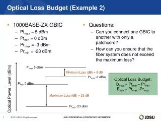
Optical network attenuation Without amplification, the maximum allowable loss in an all-optical network is given by the difference between the launch power and the receiver sensitivity. Allowable loss (dB) = Tx_power – Rx_sensitivity Of course, this value is true only if we connect transponders directly to the transmission fiber.
Optical network attenuation It is very useful to be able to specify in dB an absolute power wi watts or in mW To do this the power P2 in the dB formula is fixed at some agreed reference value, so the dB value always relates to this reference power level. Allows for easy calculation of power at any point in a system Where the reference power is 1mW the power in an optical signal with a power level P is given in dB as: Power [dB] = 10 Log [P/1nW]
dBm calculation (Transitter) A transmitter laser has a measure output power of 2.3mW. What is the laser diode output power expressed in dBm? 2.3mW Transmitter laser Power [dB] = 10 Log (Power /1 mW) Power [dB] = 10 Log (2.3mW /1 mW) Power [dB] = 10 Log (2.3) = +3.61dBm
dBm calculation (Transitter) • dB and dBm can be combined in the same calculation • As shown a fiber span (inc. splices etc.) has a total attenuation of 13 dB • If the trasmitter output power is +2 dBm what is the reciver input power in dBm? +2 dBm ? dBm Reciver Transmitter Fiber span: att 13dB Reciver input [dB] = Transmitter output power – Total fiber span att. Reciver input [dB] = +2 dBm – 13 dB Reciver input [dB] = -11 dBm
Point-to-Point link attenuation calculation 3 km 5km 2 km 4 km RX TX Connection Connection Splice Connection Components Fiber SM 9/125 14 km at 0.25dB 3.5 Connector 3 pcs. at 0.5dB 1.5 Splice 6 pcs. at 0.1dB (0.15dB)0.6___ Total attenuation 5.6 dB
Point-to-Point link attenuation calculation The table contains some typical numbers, which can be used to approximate optical link budget calculations. If at all possible, real numbers from the network in question should be used.
Optical Budget Calculator • Minimum Transmit Power _________ • Minimum Receive Sensitivity - _________ • Available Power = _________ • _________ Km of cable X _________ dB/km = _________ • _________ Connectors X _________ dB/Con. = _________ • _________ Splices X _________ dB/splice = _________ • Link Margin = _________ • _________ Repair Splices X _________ dB/Splice = _________ • Safety Margin = _________ • Excess Power _________
References Reichle & De-Massari http://www.porta-optica.org