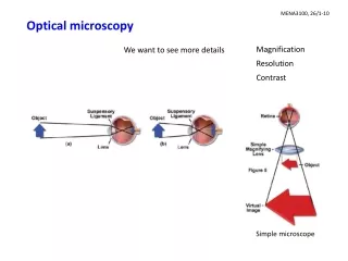
Optical Microscopy
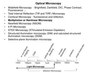
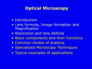
Optical Microscopy. Introduction Lens formula, Image formation and Magnification Resolution and lens defects Basic components and their functions Common modes of analysis Specialized Microscopy Techniques Typical examples of applications. Diffraction of Light.

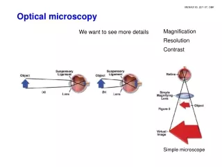
Optical Microscopy
E N D
Presentation Transcript
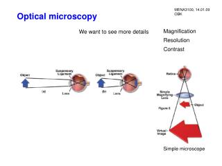
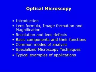
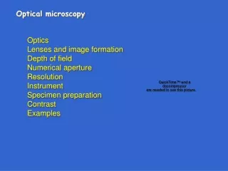
Optical Microscopy • Introduction • Lens formula, Image formation and Magnification • Resolution and lens defects • Basic components and their functions • Common modes of analysis • Specialized Microscopy Techniques • Typical examples of applications
Diffraction of Light Diffraction of light occurs when a light wave passes by a corner (or a barrier) or through an opening (or a slit) that is physically the approximate size of, or even smaller than that light's wavelength. Sin=/d /d 1st 2nd 3rd film Light waves interfere constructively and destructively.
Resolution of Microscope – Rayleigh Criteria Rayleigh Criteria: Angular separation of the two points is such that the central maximum of one image falls on the first diffraction minimum of the other =m 1.22/d
Resolution of Microscope – in terms of Linear separation • To express the resolution in terms of a linear separation r, have to consider the Abbe’s theory • Path difference between the two beams passing the two slits is • Assuming that the two beams are just collected by the objective, then i = and dmin = /2sin I II I II
Resolution of Microscope – Numerical Aperture • If the space between the specimen and the objective is filled with a medium of refractive index n, then wavelength in medium n = /n • The dmin = /2n sin = /2(N.A.) • For circular aperture dmin= 1.22/2(N.A.)=0.61/(N.A.)where N.A. = n sin is called numerical aperture Immersion oil n=1.515
Numerical Aperture (NA) NA=1 - theoretical maximum numerical aperture of a lens operating with air as the imaging medium Angular aperture (72 degrees) One half of A-A NA of an objective is a measure of its ability to gather light and resolve fine specimen detail at a fixed object distance. NA = n(sin ) n: refractive index of the imaging medium between the front lens of objective and specimen cover glass
Resolution of a Microscope (lateral) The smallest distance between two specimen points that can still be distinguished as two separate entities dmin = 0.61l/NA NA=nsin() l – illumination wavelength (light) NA – numerical aperture -one half of the objective angular aperture n-imaging medium refractive index dmin ~ 0.3m for a midspectrum l of 0.55m
Factors Affecting Resolution • Resolution = dmin = 0.61/(N.A.) • Resolution improves (smaller dmin) if or n or • Assuming that sin = 0.95 ( = 71.8°) • (The eye is more sensitive to blue than violet)
Optical Aberrations Reduce the resolution of microscope Two primary causes of non-ideal lens action: • Spherical (geometrical) aberration – related to the spherical nature of the lens • Chromatic aberration – arise from variations in the refractive indices of the wide range of frequencies in visible light Astigmatism, field curvature and comatic aberrations are easily corrected with proper lens fabrication.
Defects in Lens • Spherical Aberration – Peripheral rays and axial rays have different focal points (caused by spherical shape of the lens surfaces. • causes the image to appear hazy or blurred and slightly out of focus. • very important in terms of the resolution of the lens because it affects the coincident imaging of points along the optical axis and degrade the performance of the lens.
Defects in Lens • Chromatic Aberration • Axial - Blue light is refracted to the greatest extent followed by green and red light, a phenomenon commonly referred to as dispersion • Lateral - chromatic difference of magnification: the blue image of a detail was slightly larger than the green image or the red image in white light, thus causing color ringing of specimen details at the outer regions of the field of view A converging lens can be combined with a weaker diverging lens, so that the chromatic aberrations cancel for certain wavelengths: The combination – achromatic doublet
Axial resolution – Depth of Field Depth of focus (F mm) Depth of Field (F m) (F mm) NA F F 0.1 0.13 15.5 0.4 3.8 5.8 .95 80.0 0.19 The distance above and below geometricimage planewithin which the image is in focus The axial range through which an object can be focused without any appreciable change in image sharpness M NA F F M NA F F F is determined by NA.
camera Olympus BX51Research Microscope Cutaway Diagram Beam splitter Reflected light Transmitted light
Functions of the Major Parts of a Optical Microscope • Lamp and Condenser: project a parallel beam of light onto the sample for illumination • Sample stage with X-Y movement: sample is placed on the stage and different part of the sample can be viewed due to the X-Y movement capability • Focusing knobs: since the distance between objective and eyepiece is fixed, focusing is achieved by moving the sample relative to the objective lens
Condenser Light from the microscope light source Condenser gathers light and concentrates it into a cone of light that illuminates the specimen with uniform intensity over the entire viewfield
Functions of the Major Parts of a Optical Microscope • Objective: does the main part of magnification and resolves the fine details on the samples (mo ~ 10 – 100) • Eyepiece: forms a further magnified virtual image which can be observed directly with eyes (me ~ 10) • Beam splitter and camera: allow a permanent record of the real image from the objective be made on film
Microscope Objectives dmin = 0.61l/NA Anatomy of an objective Objective specifications rical ture Objectives are the most important components of a light microscope: image formation, magnification, the quality of images and the resolution of the microscope
Eyepiece (Diaphragm) M=(L/fo)(25/fe) Eyepieces (Oculars) work in combination with microscope objectives to further magnify the intermediate image
Common Modes of Analysis Depending on the nature of samples, different illumination methods must be used • Transmitted OM - transparent specimens • thin section of rocks, minerals and single crystals • Reflected OM - opaque specimens • most metals, ceramics, semiconductors • Specialized Microscopy Techniques • Polarized OM - specimens with anisotropic optical • character • Characteristics of materials can be determined • morphology (shape and size), phase distribution (amorphous or crystalline), transparency or opacity, color, refractive indices, dispersion of refractive indices, crystal system, birefringence, degree of crystallinity, polymorphism and etc.
camera Olympus BX51Research Microscope Cutaway Diagram Beam splitter Reflected light Transmitted light
Polarization of Light When the electric field vectors of light are restricted to a single plane by filtration, then the the light is said to be polarized with respect to the direction of propagation and all waves vibrate in the same plane.
1200C/30min Grain Size Examination Thermal Etching a 1200C/2h 20m b A grain boundary intersecting a polished surface is not in equilibrium (a). At elevated temperatures (b), surface diffusion forms a grain-boundary groove in order to balance the surface tension forces.
Grain Size Examination Objective Lens x100
Grain Growth - Reflected OM 5mm 30mm Polycrystalline CaF2 illustrating normal grain growth. Better grain size distribution. Large grains in polycrystalline spinel (MgAl2O4) growing by secondary recrystallization from a fine-grained matrix
Liquid Phase Sintering – Reflective OM Amorphous phase 40mm Microstructure of MgO-2% kaolin body resulting from reactive-liquid phase sintering.
Image of Magnetic Domains Magnetic domains and walls on a (110)-oriented garnet crystal (Transmitted LM with oblique illumination). The domains structure is illustrated in (b).
Polarized Optical Microscopy (POM) Reflected POM Transmitted POM • Surface features of a microprocessor integrated circuit • Apollo 14 Moon rock
Phase Identification by Reflected Polarized Optical Microscopy YBa2Cu307-x superconductor material: (a) tetragonal phase and (b) orthorhombic phase with multiple twinning (arrowed) (100 x).
Specialized LM Techniques • Enhancement of Contrast Darkfield Microscopy Phase contrast microscopy Differential interference contrast microscopy Fluorescence microscopy-mainly organic materials • Confocal scanning optical microscopy (new) Three-Dimensional Optical Microscopy inspect and measure submicrometer features in semiconductors and other materials • Hot- and cold-stage microscopy melting, freezing points and eutectics, polymorphs, twin and domain dynamics, phase transformations • In situ microscopy E-field, stress, etc. • Special environmental stages-vacuum or gases
Contrast Contrast is defined as the difference in light intensity between the specimen and the adjacent background relative to the overall background intensity. Image contrast, C is defined by Sspecimen-Sbackgroud S C = = Sspecimen SA Sspecimenand Sbackgroud are intensities measured from specimen and backgroud, e.g., A and B, in the scanned area.
Angle of Illumination • Bright filed illumination – The normal method of illumination, light comes from above (for reflected OM) • Oblique illumination – light is not projected along the optical axis of the objective lens; better contrast for detail features • Dark field illumination – The light is projected onto specimen surface through a special mirror block and attachment in the objective – the most effective way to improve contrast. Light stop Imax-Imin Imax C= Imax Imin C-contrast
Transmitted Dark Field Illumination Oblique rays specimen I I distance distance
Contrast Enhancement OM images of the green alga Micrasterias
Crystals Growth-Interference contrast microscopy Growth spiral on cadmium iodide crystals growing From water solution (1025x).
Confocal Scanning Optical Microscopy Three-Dimensional Optical Microscopy Critical dimension measurements in semiconductor metrology w Cross-sectional image with line scan at PR/Si interface of a sample containing 0.6m-wide lines and 1.0m-thick photoresist on silicon. The bottom width, w, determining the area of the circuit that is protected from further processing, can be measured accurately by using CSOP. Measurement of the patterned photoresist is important because it allows the process engineer to simultaneously monitor for defects, misalignment, or other artifacts that may affect the manufacturing line.
Hot-stage POM of Phase Transformations in Pb(Mg1/3Nb2/3)O3-PbTiO3 Crystals (a) and (b) at 20oC, strongly birefringent domains with extinction directions along <100>cubic, indicating a tetragonal symmetry; (c) at 240oC, phase transition from the tetragonal into cubic phase with increasing isotropic areas at the expense of vanishing strip domains. n T(oC)
E-field Induced Phase Transition in Pb(Zn1/3Nb2/3)O3-PbTiO3 Crystals c a b Single domain Schematic diagram for in situ domain observa- tions. • Domain structures of PZN-PT • crystals as a function of E-field; • E=20kV/cm, (b) e=23.5kV/cm • (c) E=27kV/cm • Rhombohedral at E=0 and • Tetragonal was induced at E>20kV/cm
Review - Optical Microscopy • Use visible light as illumination source • Has a resolution of ~o.2m • Range of samples characterized - almost unlimited for solids and liquid crystals • Usually nondestructive; sample preparation may involve material removal • Main use – direct visual observation; preliminary observation for final charac-terization with applications in geology, medicine, materials research and engineering, industries, and etc. • Cost - $15,000-$390,000 or more
Characteristics of Materials Can be determined By OM: morphology (shape and size), phase distribution (amorphous or crystalline), transparency or opacity, color, refractive indices, dispersion of refractive indices, crystal system, birefringence, degree of crystallinity, polymorphism and etc.
Limits of Optical Microscopy • Small depth of field <15.5mm • Rough surface • Low resolution ~0.2mm • Shape of specimen • Thin section or polished surface Cover glass specimen Glass slide resin 20mm • Lack of compositional and crystallographic information
Optical Microscopy vs Scanning Electron Microscopy 25mm radiolarian OM SEM Small depth of field Low resolution Large depth of field High resolution http://www.mse.iastate.edu/microscopy/