Fluorescence microscopy I Basic concepts of optical microscopy
290 likes | 392 Vues
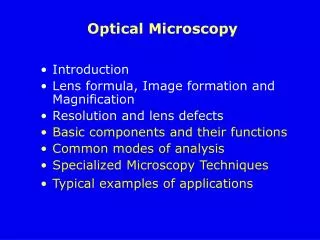
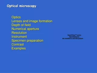
Learn about the principles of optical microscopy, fluorescence, and image contrast in the context of microscopy techniques. Understand bright-field, phase contrast, and dark-field microscopy. Explore objectives, immersion liquids, and sources of image contrast. Discover how to achieve optimal resolution and contrast in microscopy. Expand your knowledge with recommended readings and resources.

Fluorescence microscopy I Basic concepts of optical microscopy
E N D
Presentation Transcript
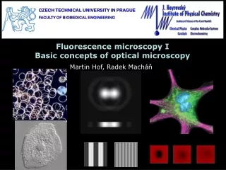
CZECH TECHNICAL UNIVERSITY IN PRAGUE FACULTY OF BIOMEDICAL ENGINEERING Fluorescence microscopy IBasic concepts of optical microscopy Martin Hof, Radek Macháň
Further reading: • Introduction to Confocal Microscopy and Image Analysis, J. P. Robinson, http://tinyurl.com/2dr5p • Molecular Expressions Microscopy Primer http://micro.magnet.fsu.edu/primer/index.html • Nikon Microscopy Tutorials, http://www.microscopyu.com/ • Zeiss Microscopy Tutorials, http://zeiss-campus.magnet.fsu.edu/index.html • Olympus Microscopy Tutorials, http://www.olympusmicro.com/, http://www.olympusfluoview.com/index.html/ • Stowers Institute Tutorials (especially FCS) http://research.stowers-institute.org/microscopy/external/Technology/index.htm
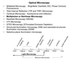
Sources of image contrast: Why do we see the objects? Because they differ in optical properties from the background: • Absorption (bright field – the “basic” optical microscopy) • Refractive index (refraction, scattering, phase shift) • Emission (fluorescence) • Raman scattering • Others (birefringence, reflection, …)
Bright field microscopy: light form the condenser passes through the sample, where it is attenuated by absorbing objects
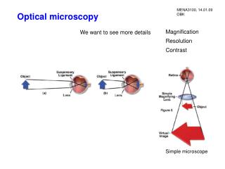
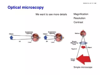
Bright field microscopy: light form the condenser passes through the sample, where it is attenuated by absorbing objects Magnification = M(objective) x M(eyepiece) the image formed by the objective in its back focal plane (the intermediate image plane) contains all information accessible by the microscope. Further magnification of the image by eyepiece or lenses of a camera only change it size for easier observation or to fit to the chip of the camera, but do not add any information. ocular We will forget about the eyepiece and magnification. The objective and the resolution and contrast it can achieve are essential objective light
A. Köhler (1866-1948) Köhler illumination – conjugated planes: optimal adjustment of theillumination pathway uses the concept of two sets of conjugated planes (planes in which the beam is simultaneously focused) to ensure even illumination of the sample
Objectives – infinity system: tube lens Inserted optical components (filters, polarizers, …) do not disturb the optical path
Objectives – aberrations and corrections: Chromatic aberration is corrected by combination of lenses of different refractive index (Achromat – 2 different wavelength focused to 1 point, Apochromat – 3 different wavelength focused to 1 point Flat-Field correction ensures planarity of the image – important for its projection on a chip of a camera
TR = 41° NA = n sin Objectives – numerical aperture: Dry objective the width of the acceptance cone of the objective determines how much light contributes to the image formation and it is important for the resolution and contrast of the image Why refractive index n??? Refraction occurring of the interface of glass (cover glass of the sample) and air Immersion liquid reduces the refractive index mismatch Immersion objective
Objectives – immersion liquids: immersion oils – chosen to match closely the refractive index of glass nG = 1.52 water – nW = 1.33, worse match, however, biological samples consist mainly of water and water immersion is better for imaging thick biological samples objectives have corrections for aberrations introduced by the cover glass of given thickness and refractive index. oil vs. water
Sources of image contrast: Bright field microscopy is based on absorption of light in the sample. Most biological objects, however, absorb only weakly in the visible spectrum. This lead to: • Development of specific staining (nowadays almost entirely replaced by fluorescent labeling) • Development of UV microscopy (Köhler) facing technical difficulties due to absorption of UV light by glass • Use of difference in refractive index between the object and medium manifested by: • refraction (scattering) of light • introduction of phase shift to the passing light
Dark field microscopy: • part-illumination of the specimen • scattered light collected by objective • bright object on dark background Objects with a sharp rise in refraction index
image plane positive phase contrast objective back focal plane & phase plate annular diaphragm pinhole specimen (phase object) condenser condenser front focal plane condenser aperture Phase contrast microscopy: positive phase contrast: object of higher optical path appears darker Frits Zernike (1888-1966) uncertainty in image interpretation arises when objects induce larger phase shift than p/2 or when absorption appears simultaneously to phase shift
0 0 A’’ B’’ A’ B’ A’’ A’ A Differential interference contrast: brightness profile in the differential image (eyepiece) analyser (- 45) local phase differences in the overlapping images revealed by the analyser doubled image individual phase profiles in the polarised components of the doubled image Wollaston prisms WPO and WPC WPO - beamsplitter a prism-induced phase differential between the two perpendicularly polarised wavefronts objective object-induced phase shift specimen the lateral profile of the object optical thickness condenser Objects appear as if illuminated from one side WPC - compensator iris diaphragm polariser (+45)
Kidney tissue(tubule with some cells> 100 µm thick section) Phase contrast vs. DIC: Buccal epithelial cell (monolayer) Phase contrast Images suffer from a halo of bright light surrounding some objects – caused by a fraction of diffracted light which has passed the phase ring DIC • Can resolve differences in thickness down to about 2 nm • Small gradients of thickness give little contrast (with modification http://mikroskopie.de)
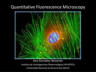
Fluorescence Microscopy: High sensitivity – single molecule observation possible Possibility of molecule-specific labeling – chemical sensitivity Fluorescence is sensitive to environment – provides information on polarity, pH, … Example: Cytoskeleton (tubulin antibody-Alexa647) Mitochondria (streptavidin-Alexa488) Nucleus (Hoechst-DNA intercalator)
Fluorescence microscope: Epi-Fluorescence setup: excitation light passes through the same objective which collects the fluorescence camera objective sample sets of filters and dichroics are available for every common fluorophore
Fluorescence microscope: Typically the inverted setup – objective below the sample Sample chamber can be open – we can add something during the measurement Many cell strands tend to adhere to the bottom of the chamber camera
E1 Photobleaching in fluorescence microscopy: source of artefacts and irreproducibility, low excitation intensity to avoid photobleaching and saturation It can be however used to investigate molecular diffusion: Fluorescence recovery after photobleaching (FRAP) – how fast are fluorophores, which had been photobleached by a pulse of high intensity, replaced by new ones lipid bilayer adsorbed to solid surface – mobile lipids lipid monolayer adsorbed to immobilized alkyl chains – immobile lipids D found by fitting the recovery curve with a model accounting for the size and shape of the bleached area I∞ I0 IB Fraction of immobile fluorophores microscopy.duke.edu/gallery.html
240 240 200 200 160 160 120 120 80 80 40 40 0 0 250 300 50 100 150 200 50 100 150 200 250 Microscope resolution – Rayleigh criterion: Light from a point source is diffracted by the objective forming an Airy disc, the size of which depends on l and NA of the objective Airy disc Corresponding intensity profile Digital contrast enhancement of images may help resolution of closer points. The improvement may be, however, overestimated due to smaller distance between the maxima than between the centers of Airy discs Rayleigh criterion: points are resolvable if the maximum of one Airy disc corresponds with the first minimum of the adjacent Airy pattern
Microscope resolution – Rayleigh criterion: Y R a a’ Y’ a q a’ Diffraction sinq = 0.61'/R Rayleigh criterion Y' = a' tanq Abbe Sine Condition: Y n sin = Y' n' sin‘ Y' n' tan‘ Ymin = 0.61 / nsin considering that ‘ = / n’ Simple geometry yields: R/a’ = tan’ Y' = 0.61'/tan’ NA
f d c b a e Microscope resolution – Abbe’s theory: Light passing through a periodic structure in the sample (a diffraction grating) results in a characteristic diffraction pattern in the objective back focal plane. The observable number of diffraction maxima is determined by NAof the objective diffraction pattern & mask Ideal image image brightness profile image appearance Description by Fourier optics: Wavefront in the back focal plane W is a Fourier transform of the object transmission functionO. The image I is the inverse Fourier transform of W W = F (O) I = F-1(W) = F-1(F(O))
Microscope resolution – Abbe’s theory: Description by Fourier optics: Wavefront in the back focal plane W is a Fourier transform of the object transmission functionO. The image I is the inverse Fourier transform of W W = F (O) I = F-1(W) = F-1(F(O)) The objective aperture filters out higher order diffraction maxima from W and, thus, filters out high spatial frequencies from I Any aperiodic objectO can be theoretically described as an infinite series of periodic functions (Fourier series) Light Microscopy in Biology. A practical Approach. A.J.Lacey (ed.), IRL Press, Oxford, 1989, p.33.
Abbe’s theory and oblique illumination: With oblique illumination higher orders of diffraction maxima can enter the objective of the same NA than with axial illumination Improved resolution However, less light enters the objective worse contrast
Microscope resolution – Elastic scattering: The shape of polar scattering diagrams for small spherical particles depends on the size of the particle r and l. The smaller r, the more symmetric is the scattering diagram. The size of the central scattering lobe corresponds to the acceptance angle of the microscope when r ≈ 3 d r ≈ d/3 r ≈ d
Microscope resolution – Summary: The lateral resolution of an optical microscope d: The axial resolution (in the direction of optical axis) dz: Sufficient contrast is necessary for full utilization of the available resolution
Acknowledgement The course was inspired by courses of: Prof. David M. Jameson, Ph.D. Prof. RNDr. Jaromír Plášek, Csc. Prof. William Reusch Financial support from the grant: FRVŠ 33/119970