Optical Microscopy
Optical Microscopy. Lecture 1. Concepts we will discuss in this lecture: . Natures of light Mechanism of Optical Imaging system The Use of Lenses and the Problem of Lenses Spatial Resolution. Some Properties of Light. Both lasers and white light sources used in microscopy. Laser.

Optical Microscopy
E N D
Presentation Transcript
Optical Microscopy Lecture 1
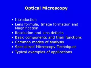
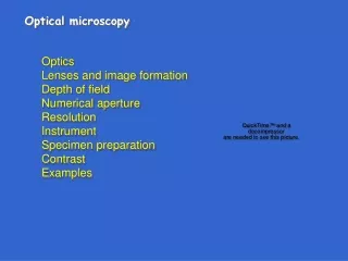
Concepts we will discuss in this lecture: • Natures of light • Mechanism of Optical Imaging system • The Use of Lenses and the Problem of Lenses • Spatial Resolution
Some Properties of Light Both lasers and white light sources used in microscopy Laser White light Chromatic Polarization Phase Direction
Monochromatic vs white light 450 nm 600 nm White light contains all, or most, of the colors of the visible spectrum. Lasers are Monochromatic (very narrow frequency distribution) Both white light, lasers used in microscopy techniques
Polarization of Light Plane where electric field vector lies, E=Eºcos(ωt) Perpendicular to direction of propagation s= horizontal p= vertical Vertical for propagation Parallel to floor Circular polarization: H,V (s,p) 90 degrees out of phase horizontal elliptical polarization: less than 90 out of phase This nature used extensively In microscopy: pol microscopy, DIC, SHG
Particle (Quantized) Behavior • Light interacting with matter: absorption, reflection • photon smallest unit- energy corresponds to frequency () • h=6x10-34 J*s Planks constant • ~10-19 J for visible light (=600 nm) • best for describing absorption, emission of light • Best for describing how detectors work (photomultipliers, Diodes)
Wave Behavior Constructive, destructive interference 0, 180 degrees Limiting cases for complete constructive, Destructive interference, respectively Underlies image formation in almost all forms of microscopy: phase, DIC, polarization, Some advanced forms of confocal
Representations of Light Absorption, lasers Interference, Image formation Good for modeling Light propagation: Ray Tracing Not real form Wave, particle duality physically important Some phenomenon described by both
Hooke made the first optical microscope Robert Hooke
Converging (focusing) Lens • The parallel rays converge at the second focal point F‘. • The first focal point is at the front. All rays originated at • This point become parallel to the axis after the lens.
Diverging (defocusing) Lens Focal length is negative To an eye on the right-hand side, these diverging rays will Appear to be coming from the point F’: the second focal point.
medium index air (STP) 1.00029 water (20° C) 1.33 crown glass 1.52 flint glass 1.65 Snell’s Law where q1 is the angle of incidence, q2 is the angle of refraction
Ray Tracing Rules for locating image Only need 2 rays
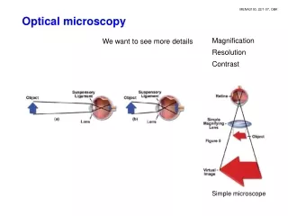
Single-lens Imaging system Real image: if rays intersect and unite in image plane and can be projected onto some surface in image plane Two-lens Imaging system Virtual Image: if rays diverge, but backwards extensions converge and intersect behind specimen
A slightly more complicated imaging system aka old microscope Eye is part of optical system of microscope
Infinity Corrected Microscopes: last 15 Years Infinity optics allows insertion of Filters, analyzers without changing tube length, or final image Infinity=parallel
Thin lens formula Basic Formulae in air Object plane Image plane Lensmakers equation
Some Conventions • S is distance from the object; S’ is distance from the image • Sign conventions: m = positive for inverted image; negative for upright • Sign conventions: f = positive for converging lens; negative for diverging lens
Inverted vs Upright Geometries • Upright: • Move stage for focusing (unless fixed stage) • Optical path is simpler • Easier for immersion (long working distance) • Inverted: • Move objective for focusing • Better access for live cells in culture • Electrophysiology • Harder for oil, water immersion.
Refractive Index Depends on the Wavelength This is called dispersion
How to Calculate? Sellmeier Equations All but quartz Quartz These values are tabulated (e.g. CVI Laser, Melles Griot)
Doublet Lens Corrects Aberration Crown Flint
Spherical Aberration could also be caused by the use of the cover glass-slip. A correction collar might be found on the objective to set the thickness of the glass-slip. If no correction collar can be found, the objective is corrected for a 0.17 mm glass-slip.
Astigmatism and coma are caused by imperfection in the lens manufacturing.
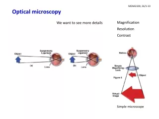
What’s Important for a Microscope? • Contrast is necessary to detect detail from background light from an object must either be different in intensity or color (= wavelength) from the background light: Both used in light and fluorescence microscopy • Resolution fundamentally limited by diffraction diffraction occurs at the objective lens aperture
l n sinq Numerical Aperture (N.A.) q specimen Objective lens Image plane From diffraction theory d N.A. = n sinq Minimum spot NA= radius/focal length ~250 nm in visible Abbe` Limit Resolution only determined by NA and wavelength
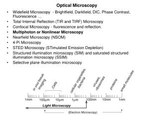
Electromagnetic Spectrum Visible region used for Light microscopy small Part of EM spectrum Resolution limit :λ/2 ~200 nm: Visible good for Live specimens: Cells, organelles Ideal for micron sized structures EM, X-ray cannot do live imaging
Consider microscope object as simple grating Spacing of Grating and Diffraction Pattern S=3 microns S=12 microns Inverse relationship (transform) of object spacing (or size) and diffraction pattern
Double-slit Experiment Condition for Constructive interference: a sinθ = nλ n = 0, 1, 2, 3 … Afterfocusing: d = f λ / a
d1 Tube Lens Fringe spacing in the image: d2 = f’ λ / d1 = f’ λ a / f λ = M a Requires at least one of the first order diffraction spot in order to form the image.
Diffracted Spots in back focal plane • No specimen diffraction: no image • Specimen diffraction: no collection, no image • 0th and first order diffraction • 0th and first and second order diffraction • better resolution Abbe showed need for central and diffracted spot