Lecture-3 Optical Microscopy
620 likes | 1.26k Vues
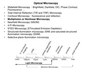
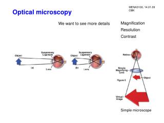
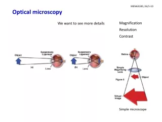
Lecture-3 Optical Microscopy. Introduction Lens formula, Image formation and Magnification Resolution and lens defects Basic components and their functions Common modes of analysis Specialized Microscopy Techniques Typical examples of applications.

Lecture-3 Optical Microscopy
E N D
Presentation Transcript
Lecture-3 Optical Microscopy • Introduction • Lens formula, Image formation and Magnification • Resolution and lens defects • Basic components and their functions • Common modes of analysis • Specialized Microscopy Techniques • Typical examples of applications http://www.youtube.com/watch?v=P2teE17zT4I&list=PLKstG-8VPWKzOe4TkvA7F6qMlG2HH8meX at~0:46-1:33
Review Problems on Optical Microscopy 1. Compare the focal lengths of two glass converging lenses, one with a larger curvature angle and the other with a smaller curvature angle. 2. List the parameters that affect the resolution of optical microscopes. 3. A student finds that some details on the specimen cannot be resolved even after the resolution of the microscope was improved by using the oil immersion objective. The student thinks that the details can be resolved by enlarging a photograph taken with the microscope at maximum magnification. Do you agree? Justify your answer. http://www.doitpoms.ac.uk/tlplib/optical-microscopy/questions.php
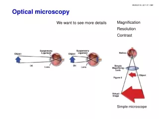
Resolution of a Microscope (lateral) http://micro.magnet.fsu.edu/primer/java/microscopy/immersion/index.html The smallest distance between two specimen points that can still be distinguished as two separate entities dmin = 0.61l/NA NA=nsin() l – illumination wavelength (light) NA – numerical aperture -one half of the objective angular aperture n-imaging medium refractive index dmin ~ 0.3m for a midspectrum l of 0.55m https://www.youtube.com/watch?v=n2asdncMYMo at~5:35-6:00
Numerical Aperture (NA) NA=1 - theoretical maximum numerical aperture of a lens operating with air as the imaging medium NA = n(sin ) n: refractive index of the imaging medium between the front lens of objective and specimen cover glass Objective lens Angular aperture (72 degrees) One half of A-A Specimen cover glass NAof an objective is a measure of its ability to gather light and resolve fine specimen detail at a fixed object distance. https://en.wikipedia.org/wiki/Angular_aperture http://micro.magnet.fsu.edu/primer/java/microscopy/immersion/index.html
NA = n(sin ) Numerical Aperture Imaging Medium Air n=1.0 Immersion oil n=1.515 http://www.youtube.com/watch?v=RSKB0J1sRnU oil immersion objective use in microscope at~0:33
Axial resolution – Depth of Field Depth of focus (f mm) Depth of Field Ranges (F m) (F mm) NA f F 0.1 0.13 15.5 0.4 3.8 5.8 .95 80.0 0.19 The distance above and below geometricimage planewithin which the image is in focus The axial range through which an object can be focused without any appreciable change in image sharpness M NA fF M NA fF F is determined by NA. http://www.matter.org.uk/tem/depth_of_field.htm http://www.youtube.com/watch?v=FvC2WLUqEug at~3:40
Depth of Focus The distance above and below geometric image plane within which the image is in focus. Depth of focus (f mm) CCD camera
Axial resolution – Depth of Field The axial range through which an object can be focused without any appreciable change in image sharpness. Depth of focus (f mm) NA f F 0.1 0.13 15.5 0.4 3.8 5.8 .95 80.0 0.19 25m Small F Large F
Basic components and their functions http://www.youtube.com/watch?v=RKA8_mif6-E Microscope Review (simple, clear) http://www.youtube.com/watch?v=b2PCJ5s-iyk Microscope working in animation (How to use a microscope) http://www.youtube.com/watch?annotation_id=annotation_100990&feature=iv&src_vid=L6d3zD2LtSI&v=ntPjuUMdXbg (I) http://www.youtube.com/watch?v=VQtMHj3vaLg (II) Parts and Function of a Microscope (details) http://www.youtube.com/watch?v=X-w98KA8UqU&feature=related How to use a microscope (specimen preparation at~1:55-2:30) http://www.youtube.com/watch?v=bGBgABLEV4g How to care for and operate a microscope
Basic components and their functions (1) Eyepiece (ocular lens) (2) Revolving nose piece (to hold multiple objective lenses) (3) Objective lenses (4) And (5) Focus knobs (4) Coarse adjustment (5) Fine adjustment (6) Stage (to hold the specimen) (7) Light source (lamp) (8) Condenser lens and diaphragm (9) Mechanical stage (move the specimen on two horizontal axes for positioning the specimen)
Functions of the Major Parts of a Optical Microscope • Lamp and Condenser: project a parallel beam of light onto the sample for illumination • Sample stage with X-Y movement: sample is placed on the stage and different part of the sample can be viewed due to the X-Y movement capability • Focusing knobs: since the distance between objective and eyepiece is fixed, focusing is achieved by moving the sample relative to the objective lens
Condenser Light from the microscope light source Condenser gathers light and concentrates it into a cone of light that illuminates the specimen with uniform intensity over the entire viewfield http://www.youtube.com/watch?annotation_id=annotation_100990&feature=iv&src_vid=L6d3zD2LtSI&v=ntPjuUMdXbg ~8:08 to 9:40 http://micro.magnet.fsu.edu/primer/java/kohler/contrast/index.html
Specimen Stage http://micro.magnet.fsu.edu/primer/flash/stage/index.html
Functions of the Major Parts of a Optical Microscope • Objective: does the main part of magnification and resolves the fine details on the samples (mo ~ 10 – 100) • Eyepiece: forms a further magnified virtual image which can be observed directly with eyes (me ~ 10) • Beam splitter and camera: allow a permanent record of the real image from the objective be made on film (for modern research microscope)
camera Olympus BX51Research Microscope Cutaway Diagram Beam splitter Reflected light Transmitted light http://micro.magnet.fsu.edu/primer/java/microassembly/index.html
Objective Lens dmin = 0.61l/NA Anatomy of an objective Objective specifications rical ture DIC-differential interference contrast Objectives are the most important components of a light microscope: image formation, magnification, the quality of imagesand the resolutionof the microscope http://www.youtube.com/watch?v=P0Z4H2O_Stg Objectives to~5:26 http://www.youtube.com/watch?v=H8PQ9RMUoA8 Grades of objectives to~2:30 & 3:25-4:50 https://www.youtube.com/watch?v=FwBjpi8ck1Y Alignment of OM
Defects in Lens • Curvature of Field - When visible light is focused through a curved lens, the image plane produced by the lens will be curved • The image appears sharp and crisp either in the center or on the edges of the viewfield but not both http://micro.magnet.fsu.edu/primer/java/aberrations/curvatureoffield/index.html
Defects in Lens • Chromatic Aberration • Axial - Blue light is refracted to the greatest extent followed by green and red light, a phenomenon commonly referred to as dispersion • Lateral - chromatic difference of magnification: the blue image of a detail was slightly larger than the green image or the red image in white light, thus causing color ringing of specimen details at the outer regions of the field of view A converging lens can be combined with a weaker diverging lens, so that the chromatic aberrations cancel for certain wavelengths: The combination – achromatic doublet weaker diverging lens http://www.youtube.com/watch?v=yH7rbRu7Av8&list=PL02D1D436A44B521A chromatic aberration http://www.youtube.com/watch?v=H8PQ9RMUoA8 at~3:30-4:30
Eyepiece Lens (Diaphragm) M=(L/fo)(25/fe) Eyepieces (Oculars) work in combination with microscope objectives to further magnify the intermediate image http://micro.magnet.fsu.edu/primer/anatomy/oculars.html http://www.birdwatching.com/optics/diopter_set.html
Lecture-3 Optical Microscopy • Introduction • Lens formula, Image formation and Magnification • Resolution and lens defects • Basic components and their functions • Common modes of analysis • Specialized Microscopy Techniques • Typical examples of applications
Depending on the nature of samples, different illumination methods must be used Common Modes of Analysis • Transmitted OM - transparent specimens thin section of rocks, minerals and single crystals • Reflected OM - opaque specimens most metals, ceramics, semiconductors Specialized Microscopy Techniques • Polarized LM - specimens with anisotropic optical character Characteristics of materials can be determined morphology (shape and size), phase distribution (amorphous or crystalline), transparency or opacity, color, refractive indices, dispersion of refractive indices, crystal system, birefringence, degree of crystallinity, polymorphism and etc.
Anatomy of a modern OM http://www.youtube.com/watch?v=7-Tlyd7piSM Trans OM to~1:37 Refle OM from 1:38-end Illumination System Reflected OM Transmitted OM Illumination System http://www.youtube.com/watch?v=zq13e36cs3s at~0:20-1:40 Field diaphragm
camera Olympus BX51Research Microscope Cutaway Diagram Beam splitter http://micro.magnet.fsu.edu/primer/java/microassembly/index.html
Depending on the nature of samples, different illumination methods must be used Common Modes of Analysis • Transmitted OM - transparent specimens thin section of rocks, minerals and single crystals • Reflected OM - opaque specimens most metals, ceramics, semiconductors Specialized Microscopy Techniques • Polarized LM - specimens with anisotropic optical character Characteristics of materials can be determined morphology (shape and size), phase distribution (amorphous or crystalline), transparency or opacity, color, refractive indices, dispersion of refractive indices, crystal system, birefringence, degree of crystallinity, polymorphism and etc.
Polarized light microscope is designed to observe specimens that are visible primarily due to their optically anisotropic character (birefringent). The microscope must be equipped with both a polarizer, positioned in the light path somewhere before the specimen, and an analyzer (a second polarizer), placed in the optical pathway between the objective rear aperture and the observation tubes or camera port. Polarized Light Microscopy birefringent - doubly refracting
Polarization of Light http://www.youtube.com/watch?v=rbx3K1xBxVU polarized light When the electric field vectors of light are restricted to a single plane by filtration, then the the light is said to be polarized with respect to the direction of propagation and all waves vibrate in the same plane. http://www.youtube.com/watch?v=lZ-_i82s16E&feature=endscreen&NR=1 to~3:30min http://www.youtube.com/watch?v=E9qpbt0v5Hw http://micro.magnet.fsu.edu/primer/java/polarizedlight/filters/index.html
Birefringence Birefringence is optical property of a material having a refractive index that depends on the polarization and propagation direction of light. Isotropic anisotropic CaCO3 Double Refraction (Birefringence) Anisotropic http://www.youtube.com/watch?v=WdrYRJfiUv0
AnisotropicOptical Character a Cubic (Birefringence) Crystals are classified as being either isotropic or anisotropic depending upon their optical behavior and whether or not their crystallographic axes are equivalent. All isotropic crystals have equivalent axes that interact with light in a similar manner, regardless of the crystal orientation with respect to incident light waves. Light entering an isotropic crystal is refracted at a constant angle and passes through the crystal at a single velocity without being polarized by interaction with the electronic components of the crystalline lattice. tetragonal c a Anisotropic crystals have crystallographically distinct axes and interact with light in a manner that is dependent upon the orientation of the crystalline lattice with respect to the incident light. When light enters the optical axis(c) of anisotropic crystals, it acts in a manner similar to interaction with isotropic crystals and passes through at a single velocity. However, when light enters a non-equivalent axis (a), it is refracted into two rays each polarized with the vibration directions oriented at right angles to one another, and traveling at different velocities. This phenomenon is termed "double" or "bi"refraction and is seen to a greater or lesser degree in all anisotropic crystals. http://micro.magnet.fsu.edu/primer/java/polarizedlight/crystal/index.html
Polarized light microscope is designed to observe specimens that are visible primarily due to their optically anisotropic character (birefringent). The microscope must be equipped with both a polarizer, positioned in the light path somewhere before the specimen, and an analyzer (a second polarizer), placed in the optical pathway between the objective rear aperture and the observation tubes or camera port. Polarized Light Microscopy birefringent - doubly refracting
Polarized Optical Microscopy (POM) Reflected POM Transmitted POM • Surface features of a microprocessor integrated circuit • Apollo 14 Moon rock http://micro.magnet.fsu.edu/primer/virtual/polarizing/index.html
Common Modes of Analysis Depending on the nature of samples, different illumination methods must be used • Transmitted OM - transparent specimens thin section of rocks, minerals and single crystals • Reflected OM - opaque specimens most metals, ceramics, semiconductors Specialized Microscopy Techniques • Polarized LM - specimens with anisotropic optical character Characteristics of materials can be determined morphology (shape and size), phase distribution (amorphous or crystalline), transparency or opacity, color, refractive indices, dispersion of refractive indices, crystal system, birefringence, degree of crystallinity, polymorphism and etc. http://www.youtube.com/watch?v=ulNZ3u7_J5I to ~1:05 http://www.youtube.com/watch?v=Iw734z1e6wQ to~1:30
Lecture-3 Optical Microscopy • Introduction • Lens formula, Image formation and Magnification • Resolution and lens defects • Basic components and their functions • Common modes of analysis • Specialized Microscopy Techniques • Typical examples of applications
Specialized OM Techniques • Enhancement of Contrast Darkfield Microscopy Phase contrast microscopy Differential interference contrast microscopy Fluorescence microscopy-medical & organic materials • Scanning confocal optical microscopy (relatively new) Three-Dimensional Optical Microscopy inspect and measure submicrometer features in semiconductors and other materials • Hot- and cold-stage microscopy melting, freezing points and eutectics, polymorphs, twin and domain dynamics, phase transformations • In situ microscopy E-field, stress, etc. • Special environmental stages-vacuum or gases
http://micro.magnet.fsu.edu/primer/techniques/contrast.html Contrast Contrast is defined as the difference in light intensity between the specimen and the adjacent background relative to the overall background intensity. Image contrast, C is defined by Sspecimen-Sbackgroud S C = = Sspecimen SA Sspecimen(Smax) and Sbackgroud (Smin) are intensities measured from specimen and background, e.g., A and B, in the scanned area. Cminimum~ 2% for human eye to distinguish differences between the specimen (image) and its background. http://www.youtube.com/watch?v=SVK4OkUK0Yw at~1:47-3:04
Contrast in Optical Microscope https://www.youtube.com/watch?v=L3SsxIUm0As at~2:17-3:46 Interaction of light with matter Contrast produced in the specimen by the absorption of light (directly related to the chemical composition of the absorber) and the predominant source of contrast in the ordinary optical microscope, brightness, reflectance, birefringence, light scattering, diffraction, fluorescence, or color variations have been the classical means of imaging specimens in brightfield microscopy. Enhancement of contrast by darkfield microscopy Darkfield microscopy is a specialized illumination technique that capitalizes on oblique illumination to enhance contrast in specimens that are not imaged well under normal brightfield illumination conditions. http://micro.magnet.fsu.edu/primer/virtual/virtualzoo/index.html http://www.youtube.com/watch?v=P2teE17zT4I&list=PLKstG-8VPWKzOe4TkvA7F6qMlG2HH8meX at~1:33-2:21
http://www.youtube.com/watch?v=d6jsnLIsNwI at~3:40-5:20 Angle of Illumination • Bright filed illumination – The normal method of illumination, light comes from above (for reflected OM) • Oblique illumination – light is not projected along the optical axis of the objective lens; better contrast for detail features • Dark field illumination – The light is projected onto specimen surface through a special mirror block and attachment in the objective – the most effective way to improve contrast. Light stop Imax-Imin Imax C= Imax Imin C-contrast http://www.youtube.com/watch?v=7V3nyRGeha4 Dark field microscopy http://micro.magnet.fsu.edu/primer/techniques/darkfieldreflect.html
Condenser Oblique hollow cone of light Cone of light Reflected light Light stop Bright field illumination Dark field illumination Condenser gathers light and concentrates it into a cone of light that illuminates the specimen with uniform intensity over the entire viewfield.
http://micro.magnet.fsu.edu/primer/java/darkfield/cardioid/index.htmlhttp://micro.magnet.fsu.edu/primer/java/darkfield/cardioid/index.html http://micro.magnet.fsu.edu/primer/techniques/darkfieldreflect.html reflected DF Transmitted Dark Field Illumination Oblique rays specimen Reflected beam I I Parallel beam distance distance http://www.youtube.com/watch?v=I4ZQm-CAgL8 at~5:24-8:14 http://www.youtube.com/watch?v=J2e0x7iTqTU DF and BF images
Contrast Enhancement OM images of the green alga Micrasterias
Specialized OM Techniques • Enhancement of Contrast Darkfield Microscopy Phase contrast microscopy Differential interference contrast microscopy Fluorescence microscopy-medical & organic materials • Scanning confocal optical microscopy (relatively new) Three-Dimensional Optical Microscopy inspect and measure submicrometer features in semiconductors and other materials • Hot- and cold-stage microscopy melting, freezing points and eutectics, polymorphs, twin and domain dynamics, phase transformations • In situ microscopy E-field, stress, etc. • Special environmental stages-vacuum or gases
http://www.microscopyu.com/articles/phasecontrast/phasemicroscopy.htmlhttp://www.microscopyu.com/articles/phasecontrast/phasemicroscopy.html Phase Contrast Microscopy Phase contrast microscopy is a contrast-enhancing optical technique that can be utilized to produce high-contrast images of transparent specimens, such as living cells, thin tissue slices, lithographic patterns, fibers, latex dispersions, glass fragments, and subcellular particles (including nuclei and other organelles). http://www.youtube.com/watch?v=I4ZQm-CAgL8 at~0:50-5:20 http://www.youtube.com/watch?v=WvyCg1uzG5c
Crystals Growthby Differential Interference contrast microscopy (DIC) Growth spiral on cadmium iodide crystals growing From water solution (1025x). http://www.youtube.com/watch?v=P2teE17zT4I at~23:05-30:50 http://micro.magnet.fsu.edu/primer/techniques/dic/dichome.html Fluorescence microscopy - medical & organic materials http://www.youtube.com/watch?v=iPrZ84kHH2U at~1:50-3:15 http://micro.magnet.fsu.edu/primer/techniques/fluorescence/fluorhome.html https://www.youtube.com/watch?v=BmRRYPDq4bYww.youtube.com/watch?v=n2asdncM
http://micro.magnet.fsu.edu/primer/techniques/confocal/index.htmlhttp://micro.magnet.fsu.edu/primer/techniques/confocal/index.html Scanning Confocal Optical Microscopy Confocal microscopy is an optical imaging technique used to increase optical resolution and contrast of a micrograph by adding a spatial pinhole placed at the confocal plane of the lens to eliminate out-of-focus light. Scanning confocal optical microscopy (SCOM) is a technique for obtaining high-resolution optical images with depth selectivity. (a laser beam is used) The key feature of confocal microscopy is its ability to acquire in-focus images from selected depths, a process known as optical sectioning. Images are acquired point-by-point and reconstructed with a computer, allowing three-dimensional reconstructions of topologically complex objects. http://www.youtube.com/watch?v=mrjgNyKX8-w Why confocal? to~1:05 http://www.youtube.com/watch?v=puT1ccMWKyQ at~0:40-1:36 & 2:40-2:56 http://www.youtube.com/watch?v=Axrst4T__YY scanning
http://www.olympusconfocal.com/theory/confocalintro.html Introductionhttp://www.olympusconfocal.com/theory/confocalintro.html Introduction Scanning Confocal Optical Microscopy Three-Dimensional Optical Microscopy Critical dimension measurements in semiconductor metrology w Cross-sectional image with line scan at PR/Si interface of a sample containing 0.6m-wide lines and 1.0m-thick photoresist on silicon. The bottom width, w, determining the area of the circuit that is protected from further processing, can be measured accurately by using SCOP. Measurement of the patterned photoresist is important because it allows the process engineer to simultaneously monitor for defects, misalignment, or other artifacts that may affect the manufacturing line. http://www.youtube.com/watch?v=oluJW7uK7rw&index=12&list=PL200E1A86911B0422 to~2.44 coral under confocal http://micro.magnet.fsu.edu/primer/virtual/confocal/index.html interactive tutorial
Lecture-3 Optical Microscopy • Introduction • Lens formula, Image formation and Magnification • Resolution and lens defects • Basic components and their functions • Common modes of analysis • Specialized Microscopy Techniques • Typical examples of applications
1200C/30min Grain Size Examination Thermal Etching a 1200C/2h 20m b A grain boundary intersecting a polished surface is not in equilibrium (a). At elevated temperatures (b), surface diffusion forms a grain-boundary groove in order to balance the surface tension forces.
Grain Size Examination Objective Lens x100 Reflected OM
Grain Growth - Reflected OM 5mm 30mm Polycrystalline CaF2 illustrating normal grain growth. Better grain size distribution. Large grains in polycrystalline spinel (MgAl2O4) growing by secondary recrystallization from a fine-grained matrix