Lecture-2 Optical Microscopy
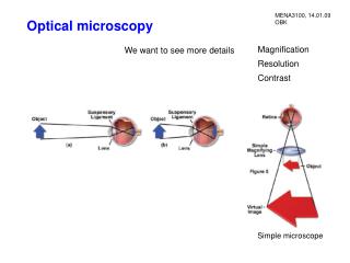
Lecture-2 Optical Microscopy. Introduction Lens formula, Image formation and Magnification Resolution and lens defects Basic components and their functions Common modes of analysis Specialized Microscopy Techniques Typical examples of applications. Basic components and their functions.

Lecture-2 Optical Microscopy
E N D
Presentation Transcript
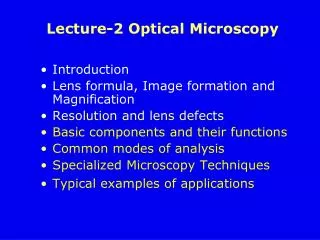
Lecture-2 Optical Microscopy • Introduction • Lens formula, Image formation and Magnification • Resolution and lens defects • Basic components and their functions • Common modes of analysis • Specialized Microscopy Techniques • Typical examples of applications
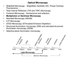
Basic components and their functions http://www.youtube.com/watch?v=PMIU1fkIPQs Microscope Review (simple, clear) http://www.youtube.com/watch?annotation_id=annotation_100990&feature=iv&src_vid=L6d3zD2LtSI&v=ntPjuUMdXbg (I) Parts and Function of a Microscope (details) http://www.youtube.com/watch?v=VQtMHj3vaLg (II) http://www.youtube.com/watch?v=X-w98KA8UqU&feature=related How to use a microscope http://www.youtube.com/watch?v=bGBgABLEV4g
Basic components and their functions (1) Eyepiece (ocular lens) (2) Revolving nose piece (to hold multiple objective lenses) (3) Objective lenses (4) And (5) Focus knobs (4) Coarse adjustment (5) Fine adjustment (6) Stage (to hold the specimen) (7) Light source (lamp) (8) Condenser lens and diaphragm (9) Mechanical stage (move the specimen on two horizontal axes for positioning the specimen)
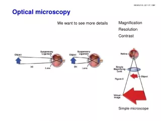
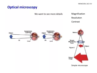
Functions of the Major Parts of a Optical Microscope • Lamp and Condenser: project a parallel beam of light onto the sample for illumination • Sample stage with X-Y movement: sample is placed on the stage and different part of the sample can be viewed due to the X-Y movement capability • Focusing knobs: since the distance between objective and eyepiece is fixed, focusing is achieved by moving the sample relative to the objective lens
Condenser Light from the microscope light source Condenser gathers light and concentrates it into a cone of light that illuminates the specimen with uniform intensity over the entire viewfield http://micro.magnet.fsu.edu/primer/java/kohler/condensercones/index.html http://micro.magnet.fsu.edu/primer/java/kohler/contrast/index.html
Specimen Stage http://micro.magnet.fsu.edu/primer/flash/stage/index.html
Functions of the Major Parts of a Optical Microscope • Objective: does the main part of magnification and resolves the fine details on the samples (mo ~ 10 – 100) • Eyepiece: forms a further magnified virtual image which can be observed directly with eyes (me ~ 10) • Beam splitter and camera: allow a permanent record of the real image from the objective be made on film (for modern research microscope)
camera Olympus BX51Research Microscope Cutaway Diagram Beam splitter
Objective Lens dmin = 0.61l/NA Anatomy of an objective Objective specifications rical ture Objectives are the most important components of a light microscope: image formation, magnification, the quality of imagesand the resolutionof the microscope http://www.youtube.com/watch?annotation_id=annotation_100990&feature=iv&src_vid=L6d3zD2LtSI&v=ntPjuUMdXbg http://micro.magnet.fsu.edu/primer/java/microscopy/immersion/index.html http://micro.magnet.fsu.edu/primer/java/nuaperture/index.html
Eyepiece Lens (Diaphragm) M=(L/fo)(25/fe) Eyepieces (Oculars) work in combination with microscope objectives to further magnify the intermediate image
Common Modes of Analysis Depending on the nature of samples, different illumination methods must be used • Transmitted OM - transparent specimens thin section of rocks, minerals and single crystals • Reflected OM - opaque specimens most metals, ceramics, semiconductors Specialized Microscopy Techniques • Polarized LM - specimens with anisotropic optical character Characteristics of materials can be determined morphology (shape and size), phase distribution (amorphous or crystalline), transparency or opacity, color, refractive indices, dispersion of refractive indices, crystal system, birefringence, degree of crystallinity, polymorphism and etc.
Anatomy of a modern OM http://micro.magnet.fsu.edu/primer/java/microscopy/reflected/index.html Illumination System Reflected OM Transmitted OM http://micro.magnet.fsu.edu/primer/java/microscopy/diaphragm/index.html Illumination System http://micro.magnet.fsu.edu/primer/java/microscopy/transmitted/index.html
Polarized light microscope is designed to observe specimens that are visible primarily due to their optically anisotropic character (birefringent). The microscope must be equipped with both a polarizer, positioned in the light path somewhere before the specimen, and an analyzer (a second polarizer), placed in the optical pathway between the objective rear aperture and the observation tubes or camera port. Polarized Light Microscopy birefringent - doubly refracting
Polarization of Light When the electric field vectors of light are restricted to a single plane by filtration, then the the light is said to be polarized with respect to the direction of propagation and all waves vibrate in the same plane. http://www.youtube.com/watch?v=lZ-_i82s16E&feature=endscreen&NR=1 ~3:30min http://micro.magnet.fsu.edu/primer/java/polarizedlight/filters/index.html
Birefringence Birefringence is optical property of a material having a refractive index that depends on the polarization and propagation direction of light. Isotropic anisotropic CaCO3 Double Refraction (Birefringence) Anisotropic http://micro.magnet.fsu.edu/primer/java/polarizedlight/icelandspar/index.html
a Cubic Birefringence Crystals are classified as being either isotropic or anisotropic depending upon their optical behavior and whether or not their crystallographic axes are equivalent. All isotropic crystals have equivalent axes that interact with light in a similar manner, regardless of the crystal orientation with respect to incident light waves. Light entering an isotropic crystal is refracted at a constant angle and passes through the crystal at a single velocity without being polarized by interaction with the electronic components of the crystalline lattice. tetragonal c a Anisotropic crystals have crystallographically distinct axes and interact with light in a manner that is dependent upon the orientation of the crystalline lattice with respect to the incident light. When light enters the optical axis(c) of anisotropic crystals, it acts in a manner similar to interaction with isotropic crystals and passes through at a single velocity. However, when light enters a non-equivalent axis (a), it is refracted into two rays each polarized with the vibration directions oriented at right angles to one another, and traveling at different velocities. This phenomenon is termed "double" or "bi"refraction and is seen to a greater or lesser degree in all anisotropic crystals. http://micro.magnet.fsu.edu/primer/java/polarizedlight/crystal/index.html
camera Olympus BX51Research Microscope Cutaway Diagram Beam splitter http://micro.magnet.fsu.edu/primer/java/microassembly/index.html
Specialized OM Techniques • Enhancement of Contrast Darkfield Microscopy Phase contrast microscopy Differential interference contrast microscopy Fluorescence microscopy-medical & organic materials • Scanning confocal optical microscopy (relatively new) Three-Dimensional Optical Microscopy inspect and measure submicrometer features in semiconductors and other materials • Hot- and cold-stage microscopy melting, freezing points and eutectics, polymorphs, twin and domain dynamics, phase transformations • In situ microscopy E-field, stress, etc. • Special environmental stages-vacuum or gases
Contrast Contrast is defined as the difference in light intensity between the specimen and the adjacent background relative to the overall background intensity. Image contrast, C is defined by Sspecimen-Sbackgroud S C = = Sspecimen SA Sspecimenand Sbackgroud are intensities measured from specimen and backgroud, e.g., A and B, in the scanned area. Cminimum~ 2% for human eye to distinguish differences between the specimen (image) and its background.
Formation of Contrast Contrast produced in the specimen by the absorption of light (directly related to the chemical composition of the absorber) and the predominant source of contrast in the ordinary optical microscope, brightness, reflectance, birefringence, light scattering, diffraction, fluorescence, or color variations have been the classical means of imaging specimens in brightfield microscopy. Enhancement of contrast by darkfield microscopy Darkfield microscopy is a specialized illumination technique that capitalizes on oblique illumination to enhance contrast in specimens that are not imaged well under normal brightfield illumination conditions. http://micro.magnet.fsu.edu/primer/virtual/virtualzoo/index.html
Angle of Illumination • Bright filed illumination – The normal method of illumination, light comes from above (for reflected OM) • Oblique illumination – light is not projected along the optical axis of the objective lens; better contrast for detail features • Dark field illumination – The light is projected onto specimen surface through a special mirror block and attachment in the objective – the most effective way to improve contrast. Light stop Imax-Imin Imax C= Imax Imin C-contrast http://micro.magnet.fsu.edu/primer/java/darkfield/reflected/index.html
Transmitted Dark Field Illumination Oblique rays specimen I I distance distance http://micro.magnet.fsu.edu/primer/java/darkfield/cardioid/index.html
Contrast Enhancement OM images of the green alga Micrasterias
Phase Contrast Microscopy Phase contrast microscopy is a contrast-enhancing optical technique that can be utilized to produce high-contrast images of transparent specimens, such as living cells, thin tissue slices, lithographic patterns, fibers, latex dispersions, glass fragments, and subcellular particles (including nuclei and other organelles). http://www.microscopyu.com/articles/phasecontrast/phasemicroscopy.html
Crystals Growthby Differential Interference contrast microscopy Growth spiral on cadmium iodide crystals growing From water solution (1025x). http://micro.magnet.fsu.edu/primer/techniques/dic/dichome.html Fluorescence microscopy - medical & organic materials http://micro.magnet.fsu.edu/primer/techniques/fluorescence/fluorhome.html
Scanning Confocal Optical Microscopy Three-Dimensional Optical Microscopy Critical dimension measurements in semiconductor metrology w Cross-sectional image with line scan at PR/Si interface of a sample containing 0.6m-wide lines and 1.0m-thick photoresist on silicon. The bottom width, w, determining the area of the circuit that is protected from further processing, can be measured accurately by using SCOP. Measurement of the patterned photoresist is important because it allows the process engineer to simultaneously monitor for defects, misalignment, or other artifacts that may affect the manufacturing line. http://www.olympusconfocal.com/theory/confocalintro.html http://micro.magnet.fsu.edu/primer/virtual/confocal/index.html
1200C/30min Grain Size Examination Thermal Etching a 1200C/2h 20m b A grain boundary intersecting a polished surface is not in equilibrium (a). At elevated temperatures (b), surface diffusion forms a grain-boundary groove in order to balance the surface tension forces.
Grain Size Examination Objective Lens x100
Grain Growth - Reflected OM 5mm 30mm Polycrystalline CaF2 illustrating normal grain growth. Better grain size distribution. Large grains in polycrystalline spinel (MgAl2O4) growing by secondary recrystallization from a fine-grained matrix
Liquid Phase Sintering – Reflective OM Amorphous phase 40mm Microstructure of MgO-2% kaolin body resulting from reactive-liquid phase sintering.
Image of Magnetic Domains Magnetic domains and walls on a (110)-oriented garnet crystal (Transmitted LM with oblique illumination). The domains structure is illustrated in (b).
Polarized Optical Microscopy (POM) Reflected POM Transmitted POM • Surface features of a microprocessor integrated circuit • Apollo 14 Moon rock http://micro.magnet.fsu.edu/primer/virtual/polarizing/index.html
Phase Identification by Reflected Polarized Optical Microscopy YBa2Cu307-x superconductor material: (a) tetragonal phase and (b) orthorhombic phase with multiple twinning (arrowed) (100 x).
Hot-stage POM of Phase Transformations in Pb(Mg1/3Nb2/3)O3-PbTiO3 Crystals (a) and (b) at 20oC, strongly birefringent domains with extinction directions along <100>cubic, indicating a tetragonal symmetry; (c) at 240oC, phase transition from the tetragonal into cubic phase with increasing isotropic areas at the expense of vanishing strip domains. n T(oC)
E-field Induced Phase Transition in Pb(Zn1/3Nb2/3)O3-PbTiO3 Crystals c a b Single domain Schematic diagram for in situ domain observa- tions. Domain structures of PZN-PT crystals as a function of E-field; • E=20kV/cm, (b) e=23.5kV/cm (c) E=27kV/cm Rhombohedral at E=0 and Tetragonal was induced at E>20kV/cm
Review - Optical Microscopy • Use visible light as illumination source • Has a resolution of ~o.2m • Range of samples characterized - almost unlimited for solids and liquid crystals • Usually nondestructive; sample preparation may involve material removal • Main use – direct visual observation; preliminary observation for final charac-terization with applications in geology, medicine, materials research and engineering, industries, and etc. • Cost - $15,000-$390,000 or more
Characteristics of Materials Can be determined By OM: Morphology (shape and size), phase distribution (amorphous or crystalline), transparency or opacity, color, refractive indices, dispersion of refractive indices, crystal system, birefringence, degree of crystallinity, polymorphism and etc.
Limits of Optical Microscopy • Small depth of field <15.5mm Rough surface • Low resolution ~0.2mm • Shape of specimen Thin section or polished surface Cover glass specimen Glass slide resin 20mm • Lack of compositional and crystallographic information
Optical Microscopy vs Scanning Electron Microscopy 25mm radiolarian OM SEM Small depth of field Low resolution Large depth of field High resolution http://www.mse.iastate.edu/microscopy/