Dynamic Modeling Techniques for Testing Interactions
Learn how to model requirements and interactions to derive test cases effectively, including decision tables, Petri Nets, and Finite State Machines. Understand static and dynamic interactions, time-dependent scenarios, and component rules to design efficient test cases. Explore the concepts of Finite State Machines, Event-Driven Petri Nets, and logic tables through practical examples.

Dynamic Modeling Techniques for Testing Interactions
E N D
Presentation Transcript
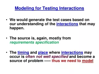
Modelingfor Testing Interactions • We would generate the test cases based on our understanding of the interactions that may happen. • The source is, again, mostly from requirements specification • The timing and place where interactions may occur is often not well specifiedand become a source of problem ----- thus we need to model
Modeling the Requirements • Concerned with entities (or constructs) interacting with each other • Every Requirement spec must specify these “basic” concepts: (as described before) • functions (actions to transform data and control) • data • events(triggers) • ports (device or source/destination of ) • threads (thread := a sequence of activities) Again, we would also need the “non-functional” (e.g. performance)
A E/R Model of 5 Interacting Entities(may not be the “ideal” model) Data 1..n input 1..n Action 1..n output 1..n 1..n Event sequenceOf 1..n 1..n Thread occur 1..n Port Would knowing these relations help in designing test cases? ----- minimal?
Interaction “Taxonomy” • Time independent interaction --- static • Time dependent interaction – dynamic • These may be either on a single processor • Or span multiple processors Most Difficult ?
Modeling Interactions(may be used for many different purposes) • Static : • Decision Tables √ √ (you have seen multiple times) • Dynamic Single Processor : • Finite State Machine √ (modeling the ATM system) • Dynamic Multiple Processors : • Petri Net (will be introduced in this lesson)
Components of a Decision Table rules R1 R2 R3 R4 R5 R6 R7 R8 T T T T F F F F C1 C2 C3 T T F F T T F F values of conditions conditions T F T F T F T F a1 a2 a3 a4 a5 x x x x x x actions taken x x actions x x x x x x R1 says when all conditions are T, then actions a1, a2, and a5 occur ---- Note that this is static; there is NO “time” or “sequence” concept
Triangle Problem Example --- “static” relation Pick input <a, b, c> for each of the columns Assume a, b and c are all between 1 and 200 • a < b + c • b < a + c • c < a + b • a = b • a = c • b = c F T T T T T T T T T T - F T T T T T T T T T - - F T T T T T T T T - - - T T T T F F F F - - - T T F F T T F F - - - T F T F T F T F • Not triangle • Scalene • Isosceles • Equilateral • “impossible” X X X X X X X X X X X Note the Impossible cases
Finite State Machine - a more formal definition(You have seen this with ATM modeling) • A Finite State Machine is composed of : • S : a set of states • Si : a special initial state from the set S • St : a subset of S called “accept” or “terminating” states • I : a set of “input symbols” or “stimulants” • T : a set of transition rules which maps S x I -> S Terminates with 11 or 00. “Accepts” strings of 1’s and 0’s that terminate with 00 or 11 1 A si 1 0 0 1 B 0 St Incorporates the notion of “time” or “sequence” --- we used this model for ATM system
Petri Net Model - Concurrency/Distributed model • A Petri Net is a model that is composed of : • P : set of places • T : set of transitions • A: Set of directed arcs which run between places and transitions; (PxT) U (TxP) [ sometimes (PxT) and (TxP) are called Inputs and Outputs] • M :Set of tokens ; initial mapping of P -> Integers P1 P4 P3 tokens t1 t2 Note that: P2 and P3 can also occur concurrently P2 There must be a token in each of the place that inputs to the transition for a transition to be “fired.” This is necessary, but may not be sufficient.
An example of “mutually” exclusive threads P1 P2 P3 t2 t1 P4 P5 Note that: t1 or t2 can occur at any time but not simultaneously in this multi-thread system. What may happen if we place 2 tokens in P2 ---- ?
Event Driven Petri Net • An Event driven Petri Net is a Petri Net with and additional set of nodes, called Events: • P : set of places • T : set of transitions • E : set of events • A: Set of directed arcs which run between places and transitions; [ (P U E) x T ] U [ T x (P u E) ] • M :Set of tokens ; initial mapping of (P U E) -> Integers P1 P4 P3 tokens t1 t2 E1 Token assignment may be key to “firing”
Consider the Example of Windshield Wiper Int is intermittent Cond 1: Lever Cond 2: dial Off Int Int Int Low High NA 1 2 3 NA NA 0 4/m 6/m 12/m 30/m 60/m # of wipes/minute Action - wiper This is a static view(no time/sequence)of the system using semi “Logic/Decision” table
Modeling Windshield Wiper with Logic/Decision Table • We would have conditions of {off, int1,int2,int3, Low and high}, the 6 conditions. So the decision table would have 26 = 64 columns of “rules” --- some are not sensible • The dial conditions is embedded in Int1, Int2, and Int3 • Actions will just be wiper speed R32 R1 T F F F F F 0 F T T T T T _ F T F F F F 4 T T T T T T _ T T T T T F _ Lever Off Lever Int1 Int2 Int3 Lever Low Lever High . . . . . . . . . . . . . 64 columns Wiper Speed
Modeling Windshield Wiper with Finite State Machine • There will be 6 states = { Off, Int1, Int2, Int3, Low, High} • “Off” state is both the starting and the terminating state • There are 4 “stimulants” = {shift-D, shift-U, turn-dial-c, turn-dial-cc} • The transitions are shown in the Finite State Diagram below Int1 Shift-D Low Shift-D High Shift-D Off Shift-U Shift-U Shift-U turn-c turn-cc turn-c; turn-cc turn-c; turn-cc turn-c; turn-cc Int2 In designing test cases with “time/sequence” consideration, you may ask what happens if you shift-D at Int2 or turn-cc (counter-clock) at Int1? Need --- “robustness” test? turn-cc Int3 turn-c
Modeling Windshield Wiper with Event Driven Petri Net • There will be 6 Places = {Off, Int1,Int2, Int3, Low, Hi} • There will be 4 Events = {S-d, S-u, T-c, T-cc} • There will be 10 transitions= {t1,----,t10} • The tokens are not be shown here since they may be mapped in too many ways here Off S-d T-cc T-cc t1 t10 t9 t8 S-u Int1 Int2 Int3 S-d t2 T-c t5 T-c Low t7 t6 S-d S-u 1)Would you generate test cases for shift-up and Int2, which is not shown? 2)Also, how would you populate the tokens? 3)How does “time” come into play for “firing” ? t3 t4 Hi S-u
Does Finite State Machine or Petri Net“help” in modeling threads and interactions? • We would generate the test cases based on our understanding of the interactions that may happen. (the expected interaction with shifting and turning of dial shown in Logic/Decision tables) • The source is mostly Requirements Specification (which may be incomplete) • *** The timing and place where interactions may occur is often not well specifiedand become a source of problem.(e.g. the shift-down or turn of dial that are not specified in the FSM or Petri Net) ***