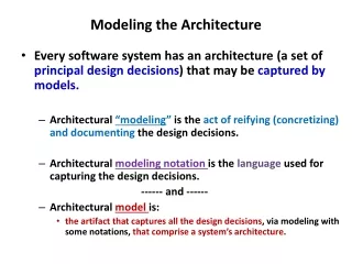
Enhancing Multi-Core Server Performance through I/O Device Virtualization and LQN Modeling
This presentation explores the promise of system virtualization on multi-core servers to address enterprise data center challenges such as server outages and energy footprint reduction. It discusses modern design approaches replacing mid-sized distributed clusters with multi-core systems, highlighting a lopsided resource approach. We dive into I/O device virtualization with a focus on independent access and QoS requirements, utilizing Layered Queuing Network (LQN) models for performance assessment and bottleneck analysis. The presentation emphasizes the importance of an adaptable simulation environment for effective model generation and evaluation.


Enhancing Multi-Core Server Performance through I/O Device Virtualization and LQN Modeling
E N D
Presentation Transcript
Modeling Architecture-OS Interactions using LQNS CADlab, SERC Indian Institute of Science Bangalore-12, India.
Promise of System Virtualization on multi-core servers. • Multi-core systems + System Virtualization → Solution to Enterprise data-center issues like server outages, real-estate and energy foot-print reduction, support for legacy applications, etc. • Current design approach of multi-core systems: • Replacement to mid-sized distributed clusters. • Facilitate compute intensive workloads (ex. scientific workloads). • Lopsided resource approach – many processors with limited I/O devices.
Characteristics of Enterprise workloads. • Workloads dominated by a mix of I/O and compute intensive jobs that are either response or throughput sensitive. • Jobs are sequential or parallel that require significantly less numbers of processors, unlike scientific workloads. • Many independent jobs require to share a common I/O device like network interface (NIC) or a storage controller. I/O Devices should enable independent, concurrent access that meets application specific QoS (performance specific) requirements.
I/O Device Virtualization - Overview Web Server Driver domain Application Server Database Server Virtual Machine Monitor NIC Hardware Para-Virtualization of I/O Devices Issues: • Two basic modes of I/O device virtualization: • Hardware virtualization using emulation. • Software/Para-virtualization using Driver domains. • QoS support on the device access path provided as an extension of system software of the hosting/driver domain. Requirement: • On multi-core servers, while consolidating I/O dominant workloads, need better ways to manage and access I/O devices without losing out on performance or usable bandwidth.
I/O Device Virtualization – XEN Virtual Machine Net Back Application Network Bridge Device Driver VM Net Front Driver Domain VMM NIC Hardware
Issues in evaluating alternative end-to-end architecture design approaches • Preferred approach • Simulation • Analytical (Maybe!) • Simulation Framework • Need for a seamless, flexible and complete system simulation environment that can allow changes in the hardware, system software (VMM and GuestOS) and allow for executing real benchmarks. • Almost all system simulators allow changes only in some of the components. • Analytical approach: Obvious difficulty in modeling shared, constrained resources and exact system and workload parameters.
Layered Queuing Network Models • Based on queuing theory principles and intuitively captures software or device contentions when multiple processes share a common software or device. • Using Method of Layers (MOL) on the LQN models, performance estimates on throughput or response times can be made. • To assess architecture capability and scalability, bottleneck analysis studies are also possible on the model. • For this study, LQNs software package developed at the RADS lab of Carleton Univ. was used. • LQM and JLQNDEF(model development tools), LQSIM (model analysis tool) and PARASRVN (tools for simulation studies on LQN models) are the different tools available. • End-to-end System architecture that is expressed using standard UML notation can be converted to LQN models.
Intuition behind using MOL solution approach on LQN Models. Ref: Method of Layers, Rolia et.Al, IEEE-Transactions of Software Engineering, vol8 aug. 1995.
Procedure used for generating LQN models • Generate software and device contention model for the end-to-end system architecture. • Expand the contention model into interaction workflow model. • Convert the workflow into LQN model.
Software and Device contention model for NIC device sharing in XEN. App2 Client App3 Client App1 Client NIC Xen-VMM Xen-IDD p0 VM1 VM2 VM3 App2 Server App1 Server App3 Server p3 p1 p2 Consolidated Server
Xen Network Packet reception workflow model. VM Device IDD Event Channels Post notify event Application 6 Receive event notification Packet Bridging 7 Copy to socket buffer 9 NetBack Device Driver NetFront Device Driver Reception I/O Ring NIC Device Driver Swap page with VM DMA data 3 8 NIC device memory Copy Forward interrupt 2 5 Packets arrive at the NIC Device Interrupt VMM NIC 1 4
Xen Network Packet transmission workflow model. VM Device IDD Event Channels Receive event notification Application 4 Post notify event 3 Packet bridging Copy data from socket buffer 1 NetBack Device Driver NetFront Device Driver Reception I/O Ring Swap page with VMM DMA data NIC Device Driver 5 2 NIC device memory Transmit packet 6 Packets sent over the network VMM NIC 7
LQNs Modeling conventions. • Each functional unit of workflow represented as an task. • A task carries out its functions using different entries. • Tasks interact with other tasks using synchronous (blocked) or asynchronous communication among their entries. • Workflow sequence of multiple independent entries within a task is captured using phases within a task. • Each task can be hosted to execute on a specified processor.
Enterprise Workload used to analyze NIC sharing in XEN - httperf • httperf is a tool for measuring web performance. Generates a mix of compute and I/O workload on the server. • Provides a flexible facility for generating various HTTP workloads and for measuring server performance. • http workloads are connection oriented tcp transactions. • Tool provides a client called “httperf” that generates a given number of http requests to a specific, standard http server, to fetch a specified file. • Benchmark workload is specified as number of http requests-per-second. • Observable metrics at the client end, that depend on the server performance, are avg. response time of replies, number of replies(received)-per-second (throughput), and errors like client timeouts, lack of file descriptors, etc. • httperf reports achieved throughput as an average of limited set of observed samples.
httperf throughput for non-virtualized and virtualized single-core system.
LQN model validation for httperf throughput. Non-Virtualized Server Virtualized Server
LQN model validation for httperf throughput. httperf throughput for two-VMs consolidated server
LQN model assumptions and result validation analysis. • In the LQN model the workload input is represented as number of http requests. In reality, the http request gets broken into network packets. Packet level queuing delays are missing in the LQN model. • In non-virtualized server there is no deviation observed. • In the case of virtualized server this causes the simulation throughput results to be optimistic (<10%). Reason is asynchronous device channels between IDD and VM. For evaluation the simulation results can be used as upper bounds on achievable throughput.
Case Study: Evaluating NIC virtualization Architecture using LQNs. Proposal of I/O device virtualization architecture - • I/O devices to be made virtualization aware; physical device should enable logical partitioning of device resources guided by QoS guarantees. • VMM to control and define a virtual device, using the logical partitioning of a device. A virtual device is exported to a VM. • The virtual device is private to a VM and is managed by the VM. IDD is eliminated.
LQN Model for NIC sharing across two VMs in Xen for the proposed I/O virtualization architecture.
httperf achievable throughout results comparison. Existing XEN architecture on a multi-core server. Proposed I/O virtualization architecture on a multi-core server.
Conclusion • Proposed I/O device virtualization architecture. • Evaluated the architecture using simulation of LQN models for httperf workload. • Architecture shows benefit of up to 60% on achievable server throughput when compared to existing Xen virtualization architecture. • Simulation results indicate similar performance when compared to real implementations.