Download
1 / 32
330 likes | 495 Vues
The fundamentals of video signals. A color space is a mathematical representation of a set of colors. The three most popular color models are RGB (used in computer graphics), YIQ, YUV or (used in video systems) and CMYK (used in color printing).

E N D
The fundamentals of video signals • A color space is a mathematical representation of a set of colors. • The three most popular color models are RGB (used in computer graphics), YIQ, YUV or (used in video systems) and CMYK (used in color printing). • However, none of these color spaces are directly related to the intuitive notions of hue, saturation and brightness. • All of the color spaces can be derived from the RGB information supplied by devices such as cameras and scanners. tMyn
Red, green and blue are three primary additive colors (individual components are added together to form a desired color) and are represented by a three-dimensional, Cartesian coordinate system, Figure 1. • The indicated diagonal of the cube, with equal amounts of each primary component, represents various gray levels. tMyn
BLUE CYAN MAGENTA WHITE BLACK GREEN RED YELLOW Figure 1a. The RGB color cube. tMyn
Table 1 contains the RGB values for color bars. Nominal range green cyan yellow white magenta blue black red 0 255 255 0 255 0 R 255 0 to 255 0 255 G 0 255 0 0 to 255 255 0 255 0 255 0 B 0 to 255 255 255 0 0 0 255 Table 1. 100% RGB color bars. tMyn
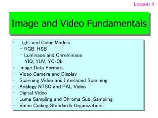
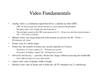
The wavelengths our eyes can detect is only a small portion of the electromagnetic energy spectrum. • It is called the visible light spectrum. • At one end of the visible spectrum are the short wavelengths of light we perceive as blue. • At the other end of the visible spectrum are the longer wavelengths of light we perceive as red. tMyn
All the other colors we can see in nature are found somewhere along the spectrum between blue and red. • Beyond the limits at each end of the visible spectrum are the short wavelengths of ultraviolet light and Xrays and the long wavelengths of infrared radiation and radio waves, which are not visible to the human eye. tMyn
If the visible portion of the light spectrum is divided into thirds, the predominant colors are red, green and blue. • These three colors are considered the primary colors of the visible light spectrum. • Primary colors can be arranged in a circle, commonly refered to as a color wheel. • Red, green and blue (RGB) form a triangle on the color wheel. • In between the primary colors are the secondary colors, cyan, magenta and yellow (CMY), which form another triangle, figure 2. tMyn
GREEN YELLOW CYAN RED BLUE MAGENTA Figure 2. The color wheel. tMyn
The additive color system involves light emitted directly from a source, before an object reflects the light. • The additive reproduction process mixes various amounts of red, green and blue light to produce other colors. • Combining one of these additive primary colors with another produces the additive secondary colors cyan, magenta and yellow. • Combining all three primary colors produces white. tMyn
Source: Wikipedia Figure 3. Additive color mixing: adding red to green yields yellow; adding yellow to blue yields white. tMyn
Television and computer monitors create color using the primary colors of light. • Each pixel on a monitor screen starts out as black. • When the red, green and blue phosphors of a pixel are illuminated simultaneously, that pixel becomes white. • This phenomenon is called additive color. • Thousands of red, green and blue phosphor dots make up the images on video monitors. • The phosphor dots emit light when activated electronically, and it is the combination of different intensities of red, green and blue phosphor dots that produces all the colors on a video monitor. tMyn
All image capture devices utilize the additive color system to gather the information needed to reproduce a color image. • However, none of these color spaces are directly related to the intuitive notions of hue, saturation and brightness. • Hue is the perceptual attribute associated with elementary color names. • Hue enables us to identify basic colors, such as blue, green, yellow, red and purple. • People with normal color vision report that hues follow a natural sequence based on their similarity to one another. tMyn
Lightness corresponds to how much light appears to be reflected from a surface in relation to nearby surfaces. • Lightness, like hue, is perceptual attribute that cannot be computed from physical measurements alone. • It is the most important attribute in making contrast more effective. • Saturation is the degree of color intensity associated with a color’s perceptual difference from a white, black or gray of equal lightness. • Figure 3 summarizes these three attributes. tMyn
Source: Wikipedia Figure 3a. Hue, lightness and saturation, the three perceptual attributes of light. tMyn
LOW LIGHTNESS GREEN YELLOW CYAN RED SATURATION BLUE MAGENTA HUE HIGH LIGHTNESS Figure 3b. Hue, lightness and saturation, the three perceptual attributes of light. tMyn
The YUV color space is used by the PAL (Phase Alternation Line), NTSC (National Television System Committee) and SECAM (Sequentiel Couleur Avec Memoire or Sequential Color with Memory) composite color video standards, Figure 4. • The black-and-white system used only luma (Y) information, color information (U and V) was added in such a way that a black-and-white receiver would still display a normal black-and-white picture. • Color receivers decoded the additional color information to display a color picture. tMyn
The basic equations to convert between gamma-corrected RGB (notated as ) and YUV are: tMyn
For digital values with a range of 0-255, Y has a range of 0-255, U a range of 0 to , and V a range of 0 to . • These equations are usually scaled to simplify the implementation in an actual NTSC or PAL digital encoder or decoder. tMyn
The transfer function of most displays produces an intensity that is proportional to some power (referred to as gamma) of the signal amplitude. • As a result, high-intensity ranges are expanded and low-intensity ranges are compressed. • This is an advantage in combatting noise, as the eye is approximately equally sensitive to equally relative intensity changes. • By ”gamma correcting” the video signals before display, the intensity output of the display is roughly linear, and transmission-induced noise is reduced. tMyn
The color space was developed as part of ITU-R BT 601 during the development of a world-wide digital component video standard, Figure 5. • The color space is a scaled and offset version of the YUV color space. • Y is defined to have a nominal 8-bit range of 16-235, and are defined to have a nominal range of 16-240. • There are several sampling formats, such as 4:2:2 and 4:2:0. tMyn
Source: Wikipedia Figure 5b. A colour image and the Y, Cb and Cr elements of it. Note that the Y image is essentially a greyscale copy of the main image; that the white snow is represented as a middle value in both Cr and Cb; that the brown barn is represented by weak Cb and strong Cr; that the green grass is represented by strong Cb and weak Cr; and that the blue sky is represented by strong Cb and weak Cr. The murkiness of the Cb and Cr elements (to the human eye) demonstrate why many image compression codecs downsample colour; details in Y are much more visible than in Cb or Cr. tMyn
The basic equations to convert between 8-bit digital data with a 16-235 nominal range and are: tMyn
When performing to conversion, the resulting values have a nominal range of 16-235, with possible occasional excursions into the 0-15 and 236-255 values. tMyn
Television services in Europe currently broadcast video at a frame rate of 25 Hz. • Each frame consists of two interlaced fields, giving a field rate of 50 Hz. • The first field of each frame contains only the odd numbered lines of the frame (numbering the top frame line as line 1). • The second field contains only the even numbered lines of the frame and is sampled in the video camera 20 msec after the first field. • It is important to note that one interlaced frame contains fields from two instants in time. tMyn
American television is similarly interlaced but with a frame rate of just under 30 Hz. • In video systems other than television, non-interlaced video is commonplace (for example, most computers output non-interlaced video). • In non-interlaced video, all the lines of a frame are sampled at the same instant in time. • Non-interlaced video is also termed ’progressively scanned’ or ’sequentially scanned’ video. tMyn
The red, green and blue (RGB) signals coming from a color television camera can be equivalently expressed as luminance (Y) and chrominance (UV) components. • The chrominance bandwidth may be reduced relative to the luminance without significantly affecting the picture quality. • For standard definition video, ”Encoding parameters of digital television for studios”, CCIR Recommendation 601, later called Recommendation ITU-R BT 601 defines how the component video signals can be sampled and digitized to form discrete pixels. tMyn
The terms 4:2:2 and 4:2:0 are often used to describe the sampling structure of the digital picture. • 4:2:2 means the chrominance is horizontally subsampled by a factor of two relative to the luminance. • 4:2:0 means the chrominance is horizontally and vertically subsampled by a factor of two relative to the luminance. tMyn
The active region of a standard digital television frame, sampled according to CCIR recommendation 601, is 720 pixels by 576 lines for a frame rate of 25 Hz. • Using 8 bits for each pixel, the uncompressed bit rates for 4:2:2 and 4:2:0 signals are therefore: 4:2:2-sampling: (720*576*25*8 + 360*576*25*8 + 360*576*25*8) bits/sec = 166 Mbits/sec. 4:2:0-sampling (720*576*25*8 + 360*288*25*8 + 360*288*25*8) bits/sec = 124 Mbits/sec. tMyn
MPEG-2 is capable of compressing the bit rate of standard-definition 4:2:0 video down to about 3-15 Mbits/sec. • At the lower bit rates in this range, the impairments introduced by the MPEG-2 coding and decoding process become increasingly objectionable. • For digital terrestrial television broadcasting of standard-definition video, a bit rate of about 4-6 Mbits/sec is thought to be a good compromise between picture quality and transmission bandwidth efficiency. tMyn