Instrumentation for scientists
570 likes | 707 Vues
This resource provides a comprehensive overview of binary arithmetic and AVR (Advanced Virtual RISC) instructions targeted at scientists. Key concepts include the binary number system, CPU operations, address and data buses, as well as the fetch-execute cycle. It also covers fundamental data types in C for embedded systems, signed/unsigned number representation, and logical operations using binary notation. The material addresses practical applications of microcontrollers and microprocessors, emphasizing their architecture, data manipulation capabilities, and examples of common instructions.

Instrumentation for scientists
E N D
Presentation Transcript
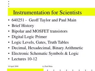
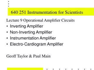
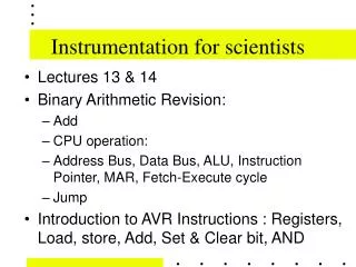
Instrumentation for scientists • Lectures 13 & 14 • Binary Arithmetic Revision: • Add • CPU operation: • Address Bus, Data Bus, ALU, Instruction Pointer, MAR, Fetch-Execute cycle • Jump • Introduction to AVR Instructions : Registers, Load, store, Add, Set & Clear bit, AND
Fundamental Data Types (1) Computers work in the binary number system. The basic unit is the bit ("BInary digIT") A bit can be either “1” or “0” (High or Low, True or False, 5 Volts or 0 Volts) The other basic units are: Nibble 4 bits 0000 - 1111 (Binary), 0 - F (Hex) Byte 8 bits 0000 0000 - 1111 1111 (Binary), 00 - FF (Hex) Word 16 bits 0000 - FFFF (Hex) Longword 32 bits 0000 0000 - FFFF FFFF (Hex)
Fundamental Data Types in C (2) Embedded “C” language (for AVR microcontrollers) char c; // signed 8 bit integer. // range: -128..127 int i; // signed 16 bit integer. // range: -32768..+32767 long int l; // signed 32 bit integer. // -2147483648..+2147483647 unsigned char u;// unsigned 8 bit number. // range: 0 .. 255 unsigned int v;// unsigned 16 bit number. // range: 0 .. 65535 unsigned long w;// unsigned 32 bit number. // range: 0 .. 4294967296
Logical Notation • AND A AND B = A B = A & B • OR A OR B = A + B = A | B • NOT NOT A = A = A# • XOR A XOR B = A B = A ^ B
Signed Number Representation Hex numbers may be signed or unsigned. Unsigned numbers are positive only. For 8 bits, they range from 0 .. 255 (0..FF hex) Signed numbers are positive, negative or zero. The most significant bit is used to represent the sign of a number For 8 bits, they range from -128 ..127 (80..7F hex)
Negative Number representation Byte numeric representation (8 bits = 1 byte) Signed Unsigned Binary Hexadecimal Octal +127 127 0111 1111 7F 177 -128 128 1000 0000 80 200 -4 252 1111 1100 FC 374 -3 253 1111 1101 FD 375 -2 254 1111 1110 FE 376 -1 255 1111 1111 FF 377
Hex & Binary Notation Normally hexadecimal numbers often have either a dollar sign '$' (some assemblers) or a ’0x' (as in C) or ah ‘H’ suffix (as in MASM/TASM) to indicate their base is 16. However, the computers we will require a $ sign. Binary numbers have a '%' sign to indicate their base. eg: %0110 1101
Binary Addition 0 + 0 = 0, 0 + 1 = 1, 1 + 0 = 1, 1 + 1 = 0, Carry 1
One's complement Invert bits - The NOT operation is performed invert 1101 0101 -> 0010 1010
Two's complement Take one's complement of a number and add 1 convert from positive to negative number convert from negative to positive number Example: Negate 1101 0101 -> 0010 1010 + 0000 0001 = 0010 1011
Two's complement 1) Start with 0000 0011 One's complement 1111 1100 Add 1 1111 1101 2) Start with 0000 0000 One's complement 1111 1111 Add 1 0000 0000
Extended IBM Graphics Character Set 0123456789ABCDEF 00 10 20 30 40 50 60 70 80 90 A0B0 C0 D0 E0F0 “char” can also represent characters - the ASCII characters are from 0..127 (0..7FHex). IBM extended the character set to include another 128 symbols- characters with various accents, box drawing characters, the Greek alphabet and some mathematic symbols.
Some Jargon (1) Processor - A processor is an electronic device capable of manipulating data in a way specified by a program. Data - A collection of information Program - A sequence of instructions Co-Processor - A processor with restricted functionality for example: Intel 80387 floating point math co-processor; Intel 8259 DMA controller. A co-processor may have the ability to take full control of the Address and Data busses.
More Jargon (2) TLAs - Three Letter Acronyms: MCU - Micro Controller Unit ALU - Arithmetic and Logic Unit ISP - In System Programmable (I.e. chip does not need to be removed from circuit for programming) I/O - Input/Output kbps - kilo bit per second = one thousand bits per second KB - Kilo Byte = 1024 bytes. MB - Mega Byte = 220 bytes = 10242 = 1048576
Microprocessors A Microprocessor is a processor implemented on (usually) one integrated circuit. A processor requires: • memory for program and data storage • support logic • Input and Output ports Data is read from and written to memory. Instructions are read from (flash) memory.
Types of Computers (1) • Von Neumann architecture • The computer follows a step-by-step program that governs its operation. • The program is stored as data • No distinction between data and instructions. • Harvard Architecture • Separate data and address spaces • The program is stored in its own address space
Types of Computers (2) • RISC - Reduced Instruction Set Computer • The instruction set is small, and most instructions complete in one cycle (100 or less instruction types, smaller range of addressing modes). • Multiply & Divide performed using add/subtract & shift • DSP - Digital Signal Processor • The instruction set is specialised for common fixed or floating point arithmetic. DSP performance is measured in MFLOPS - Millions of Floating/Fixed Point Operations Per Second.
Types of Computers (3) • CISC - Complex Instruction Set Computer • The instruction set is large, and offers great variety of instructions (100 or more instruction types, many addressing modes). • Few instructions complete in one cycle • Typically includes multiply & divide operations that may take many cycles to complete. • EG the 68HC11 takes- 10 Cycles for (8x8) MUL • 41 cycles for 16 / 16 Divide. 200K mul/sec, 50K div / sec
Types of Computers (4) Neural computer (also known as a neural network or connectionist system) - Its operation is determined by the input patterns to a system of processing elements based on the functionality of the human neuron. The neural computer is nonprogrammable (in the traditional sense), instead it learns from experience how to function.
The AVR family members (1) The AVR is a special type of microprocessor known as a microcontroller. It is designed for industrial control applications, but has many uses. The AVR family of microcontrollers ranges from a tiny 8 Pin DIP ATTINY11 with 1KB of ISP programmable flash and only 32 Registers costing under 40 cents - up to a powerful 100pin TQFP ATMEGA2560 with 256KB flash, 8KB (RAM expandable to 64KB), 8KB EEPROM, 10 bit ADC, timers, pwm outputs, costing around $20
The AVR family members (2) Special purpose peripheral versions : AT90CAN128 - MCU similar to the ATMEGA128 but incorporating (Automotive) CAN bus interface. AT90USB1287 - MCU similar to the ATMEGA128 but incorporating USB interface. AT90PWM1 - MCU similar to the ATMEGA8535 but incorporating PWM controllers specifically for lighting and motor control. ATMEGA64RZ -AVR Z-Link chipset for IEEE 802.15.4 and ZigBee wireless applications.
The AVR family members (3) New high performance 32 bit MCU/DSP AVRs : The AVR32 UC3B devices deliver 72 Dhrystone MIPS (DMIPS) at 60 MHz, and include true single-cycle MACs and DSP arithmetic and consume only 23 mA at 3.3V. DSP - Digital Signal Processor. MAC - Multiply & ACcumulate - A typical function performed by DSPs to implement Filters, Discrete/ Fast Fourier Transforms (butterfly) etc...
The AVR family members (4) New ultra low power - “Pico Power” - AVRs : ATmega48P/88P/168P/328P devices have 4, 8, 16 and 32 Kbytes of Flash memory, respectively. These devices consume as little as 340 uA in active mode at 1.8V running from the internal RC oscillator at 1 MHz, 650 nA in power-save mode with real time counter running, and 100 nA in power-down mode. I.e. a device running on 2 x AA Alkaline batteries (2500mAH) could run for 10 Months in active mode, 430 Years in power-save mode, or 2800 years on power-down mode. (roughly the shelf life of the battaries)
Programs (1) Instructions are read from program memory.(Fetch) As each instruction is decoded, it causes the processor to perform a given operation. (Execute) A self-contained sequence of instructions is a program. The AVR processor fetches one instruction at a time, and concurrentlyexecutes the previously fetched instruction.
Programs (2) Programs are also know as software The electronic components that make up a computer are called hardware. When programs are stored in ROM, EPROM, EEPROM or FLASH memory, they are called firmware
Address Space - Data Memory Addresses are numbers that point to locations in memory. The ATMEGA128 has a linear 16-bit data address bus, which means it can address 65536 RAM memory locations. Its address range is from 0000 to FFFF. It is therefore said to have a 64k data address space. The CPU registers are directly accessable in the lowest 32 memory locations.
Address Space - ata RAM The first 4352 Data Memory locations are allocated to on chip functions: The first 32 locations address the Register file, the next 64 location the standard I/O memory, then 160 locations of Extended I/O memory, and the next 4096 locations address the internal data SRAM (Static RAM).
Address Space - EEPROM EEPROM Data Memory The ATmega128 contains 4K bytes of data EEPROM memory. It is organised as a separate data space, in which single bytes can be read and written. The EEPROM has an endurance of at least 100,000 write/erase cycles. The access between the EEPROM and the CPU is by specifying the (read/write) operation using the EEPROM Address Registers, the EEPROM Data Register, and the EEPROM Control Register.
EEPROM write EEPROM_write: ; Wait for completion of previous write sbic EECR,EEWE ; skip if bit in I/O is Cleared rjmp EEPROM_write ; relative jump ; Set up address (r18:r17) in EEPROM Address Register out EEARH, r18 out EEARL, r17 ; Write data (r16) to EEPROM Data Register out EEDR,r16 ; Write logical one to EEMWE sbi EECR,EEMWE ; Start eeprom write by setting EEWE sbi EECR,EEWE ret
EEPROM read EEPROM_read: ; Wait for completion of previous write sbic EECR,EEWE rjmp EEPROM_read ; Set up address (r18:r17) in address register out EEARH, r18 out EEARL, r17 ; Start eeprom read by writing EERE sbi EECR,EERE ; Read data from data register in r16,EEDR ret
Address Space - for Programs All AVR instructions require a 16-bit (2-byte) program word. The AVR can address 65536 program flash memory locations. Its linear address range is from 0000 to FFFF. This is arranged as 64K word locations. It is therefore said to have a 64k word data address space - i.e. the ATMEGA128 has a 128KB flash Program address space arranged as 16 bit words. Every instruction fetched is 16 bits.
Program Memory Address Space Constant Data (Tables) may be stored in program FLASH memory and read, one byte at a time, using the LPM or ELPM instructions. The Z register points to Program Flash to be loaded. For example: ELPM Loads R0 with [RAMPZ:Z] (Extended Load Program Memory takes 3 clock cycles)
I/O Address Space The AVR has a separate 64 byte I/O address space for I/O ports and peripheral control registers. The I/O addresses can be accessed using IN and OUT instructions. However, the ATMEGA128 is a complex microcontroller which outgrew the original I/O space architecture allocated for smaller AVRs. So the I/O space is extended such that the extra I/O registers appear mapped into memory address space. For the Extended I/O space from $60 - $FF in SRAM, only the ST/STS/STD and LD/LDS/LDD instructions can be used.
Registers Registers are the internal storage of a processor. They hold the data the processor is currently using. For a processor to manipulate the data at a given location in memory, that data must first be loaded into a register. The data is then manipulated according to the current instruction. Registers may hold data, addresses or status information.
Busses Busses are the transportation vehicles for (electrical) signals, including both data and instructions, between registers, registers and memory locations, and among memory locations The AVR, is an 8-bit processor: the external data bus consists of 8 bits and the external address bus consists of 16 bits. The program-address and program-data busses are separate. Both consist are 16 bits, and operate concurrently and separately to the data bus.
Bit Manipulation - In I/O space • It is often necessary to alter just one bit of a register or memory location. How can this be performed? • In I/O space from 0..1F - • CBI - Clear Bit I/O • - example: CBI $12, 7 ; Clear bit 7 in Port D • SBI - Set Bit in I/O - • example: SBI $1C, 0 ; Set bit 0 in EECR ; eeprom control reg
Masking • It is often neccessary to alter just one bit of a register or memory location. How can this be performed? • AND R0, $55 • AND REGISTER R0 with 55 Hexadecimal • 55 Hexadecimal = 01010101 • A0 (A0 0), A1 (A1 1) , A2 (A2 0), A3 (A3 1), • A4 (A4 0) , A5 (A5 1), A6 (A6 0), A7 (A1 1)
Status Register (SREG) • 8 Flags - I T H S V N Z C - Reflect the results of Arithmetic & Logical operations in the CPU • N Negative result - Reflects MSB of result • Z Zero result - Set when the result is 0 (byte = 0000 0000) • V oVerflow - Twos complement overflow • C Carry (or borrow) - Used with shift & rotate instruction error flag for MUL & DIV instructions.