Download
1 / 48
500 likes | 720 Vues
Project Report On ISDN Under the Guidance of Mr. Sachin Khandelwal(S.D.E.) Submitted by: Arpit Biyani(Group leader) Shazalee Lalani Yogita Tripure Devshri Sahu Saurabh Kumar Nayak. PROJECT TEAM Project Leader: Arpit Biyani Phone: 9993334143 Email: arpitbn@gmail.com Project Members:

E N D
Project Report On ISDN Under the Guidance of Mr. Sachin Khandelwal(S.D.E.) Submitted by: Arpit Biyani(Group leader) Shazalee Lalani Yogita Tripure Devshri Sahu Saurabh Kumar Nayak
PROJECT TEAM • Project Leader: • Arpit Biyani • Phone: 9993334143 • Email: arpitbn@gmail.com • Project Members: • Shazalee Lalani • Phone: 9406252520 • Email: shazaleelalani@gmail.com • Saurabh Kumar Nayak • Phone: 8871100992 • Email: • Devshri Sahu • Phone: • Email: • Yogita Tripure • Phone: • Email:
DECLARATION We hereby declare that the Project entitled “Integrated Service Digital Network” being submitted in partial fulfillment for the certificate for vocational training to “Bharat Sanchar Nigam Limited, Durg” is the authentic record of our own work done under the guidance of Mr. Sachin Khandelwal(SDE), our project guides. Project Members: Arpit Biyani Shazalee Lalami Yogita Tripure Devshri Sahu Saurabh Kumar Nayak
ACKNOWLEDGEMENT First & foremost, we thank Almighty God for giving me this unique opportunity to express my heartfelt gratitude to all those who have extended helping hands to make this study success. We have a great pleasure in expressing my deep sense of gratitude to Mr. Sachin Khandelwal ,S.D.E. (Computer Faculty), without whose help we would never have achieved completion in our work. We would heartily like to thank DGM(CFA) and all our teachers for guiding us forth in this project. With due regards we feel immense pleasure in expressing our deepest gratitude to our amiable parents & friends whose filial affection, encouragement & blessing have been a beacon light to us in all undertakings. Date: - 4th July 2011 Submitted by: Arpit Biyani Shazalee Lalani Devshri Sahu Yogita Tripure Saurabh Kumar Nayak
CERTIFICATE This is to certify thatArpit Biyania student of Computer ScienceBranch in Natinal Institute of Technology, Raipur College has successfully completed a project on the topic-“Integrated Service Digital Network” on 4th Jul.,2011 & submitted the report on the same, under the guidance of our project guides Mr. Sachin Khandelwal, S.D.E.(computer faculty) Project Guides- Mr. Sachin Khandelwal(S.D.E.)
CERTIFICATE This is to certify thatShazalee Lalani a student of Electronics and Telecommunication Branch in Chhattisgarh Institute Of Technology, RajnandgaonCollege has successfully completed a project on the topic- “Integrated Service Digital Network” on 4th Jul.,2010 & submitted the report on the same, under the guidance of our project guides Mr. Sachin Khandelwal, S.D.E.(computer faculty) Project Guides- Mr. Sachin Khandelwal(S.D.E.)
CERTIFICATE This is to certify thatSaurabh Kumar Nayaka student of Electronics and Telecommuniction Branch in Garv Institute of Technology College has successfully completed a project on the topic-“Integrated Service Digital Network” on 4th Jul.,2010 & submitted the report on the same, under the guidance of our project guides Mr. Sachin Khandelwal, S.D.E.(computer faculty). Project Guides- Mr. Sachin Khandelwal(S.D.E.)
CERTIFICATE This is to certify thatYogita Tripurea student of ……………………………. Branch in ……………………………… ………………… …………………… College has successfully completed a project on the topic- “Integrated Service Digital Network”on 4th Jul.,2010 & submitted the report on the same, under the guidance of our project guides Mr. Sachin Khandelwal, S.D.E.(computer faculty). Project Guides- Mr. Sachin Khandelwal(S.D.E.)
CERTIFICATE This is to certify that Devshri Sahu a student of ………………………. Branch in ……………………………… ………………… …………………… College has successfully completed a project on the topic- “Integrated Service Digital Network” on 4th Jul.,2010 & submitted the report on the same, under the guidance of our project guides Mr. Sachin Khandelwal, S.D.E.(computer faculty) Project Guides- Mr. Sachin Khandelwal(S.D.E.)
INDEX PAGE NO. CONTENTS….
ISDN Integrated Services Digital Network (ISDN) is a set of communications standards for simultaneous digitaltransmission of voice, video, data, and other network services over the traditional circuits of the public switched telephone network. It was first defined in 1988 in the CCITT red book.[1] Prior to ISDN, the phone system was viewed as a way to transport voice, with some special services available for data. The key feature of ISDN is that it integrates speech and data on the same lines, adding features that were not available in the classic telephone system.
ISDN is a circuit-switchedtelephonenetwork system, which also provides access to packet switched networks, designed to allow digital transmission of voice and data over ordinary telephone copper wires, resulting in potentially better voice quality than an analog phone can provide. It offers circuit-switched connections (for either voice or data), and packet-switched connections (for data), in increments of 64 kilobit/s. ISDN has been specifically designed to solve the low bandwidth problems that small offices or dial-in users have with traditional telephone dial-in services. Telephone companies developed ISDN with the intention of creating a totally digitalnetwork whilst making use of the existingtelephonewiring system. ISDN works very much like a telephone - When you make a data call with ISDN, the WAN link is brought up for the duration of the call and is taken down when the call is completed. ISDN allows digitalsignals to be transmitted over existing telephone wiring.
This became possible when the telephone company switches were upgraded to handle digital signals. ISDN is generally viewed as an alternative to leasedlines, which can be used for telecommuting and networking small and remote offices into LANs. A major market application for ISDN in some countries is Internet access, where ISDN typically provides a maximum of 128 kbit/s in both upstream and downstream directions. Channel bonding can achieve a greater data rate; typically the ISDN B-channels of 3 or 4 BRIs (6 to 8 64 kbit/s channels) are bonded. ISDN should not be mistaken for its use with a specific protocol, whereby ISDN is employed as the network, data-link and physical layers in the context of the OSI model. In a broad sense ISDN can be considered a suite of digital services existing on layers 1, 2, and 3 of the OSI model. ISDN is designed to provide access to voice and data services simultaneously.
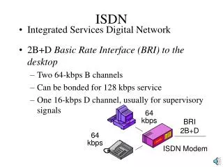
However, common use has reduced ISDN to be limited and related protocols, which are a set of protocols for establishing and breaking circuit switched connections, and for advanced call features for the user. They were introduced in 1986.In a videoconference, ISDN provides simultaneous voice, video, and text transmission between individual desktop videoconferencing systems and group (room) videoconferencing systems.ISDN provides several communication channels to customers via local loop lines through a standardized digital transmission line. ISDN is provided in two interface formats: basic rate (primarily for consumers) and high-speed rate (primarily for businesses). The basic rate interface (BRI) is 144 kbps and is divided into three digital channels called 2B + D. The primary rate interface (PRI) is 1.54 Mbps and is divided into 23B + D for North America and 2.048 Mbps and is divided into 30B + 2D for the rest of the world. The digital channels for the BRI are carried over a single, unshielded, twisted pair of copper wires and the PRI is normally carried on (2) twisted pairs of copper wire.
ISDN ARCHITECTURE This diagram shows the different interfaces are available in the integrated services digital network (ISDN). The two interfaces shown are BRI and PRI. These are all digital interfaces from the PSTN to the end customer's network termination. Network termination 1 (NT1) equipment devices can directly connect to the NT1 connection. Devices that require other standards (such as POTS or data modems) require a terminal adapter (TA). This example shows that the NT2 interface works with the NT1 interface to allow the application layers (terminal intelligence) to communicate with the ISDN termination equipment.
ISDN ADVANTAGES • The basic advantage of ISDN is to facilitate the user with multiple digital channels. These channels can operate concurrently through the same one copper wire pair. • The digital signals broadcasting transversely the telephone lines. • ISDN provides high data rate because of digital scheme which is 56kbps. • ISDN network lines are able to switch manifold devices on the single line such as faxes, computers, cash registers credit cards readers, and many other devices. • These all devices can work together and directly be connected to a single line. • ISDN takes only 2 seconds to launch a connection while other modems take 30 to 60 second for establishment. • ISDN Disadvantages • The disadvantage of ISDN lines is that it is very costly than the other typical telephone system. • ISDN requires specialized digital devices just like Telephone Company.
ISDN ELEMENTS Integrated services refers to ISDN's ability to deliver at minimum two simultaneous connections, in any combination of data, voice, video, and fax, over a single line. Multiple devices can be attached to the line, and used as needed. That means an ISDN line can take care of most people's complete communications needs (apart from broadband Internet access and entertainment television) at a much higher transmission rate, without forcing the purchase of multiple analog phone lines. It also refers to Integrated Switching and Transmission in that telephone switching and carrier wave transmission are integrated rather than separate as in earlier technology.
INTERFACES TO ISDN There are several kinds of access interfaces to ISDN defined as Basic Rate Interface (BRI), Primary Rate Interface (PRI) and Broadband ISDN (B-ISDN). • Basic Rate Interface • The entry level interface to ISDN is the Basic(s) Rate Interface (BRI), a 128 kbit/s service delivered over a pair of standard telephone copper wires. The 144 kbit/s payload rate is broken down into two 64 kbit/s bearer channels ('B' channels) and one 16 kbit/s signaling channel ('D' channel or delta channel). This is sometimes referred to as 2B+D. • The interface specifies the following network interfaces: • The U interface is a two-wire interface between the exchange and a network terminating unit, which is usually the demarcation point in non-North American networks.
The T interface is a serial interface between a computing device and a terminal adapter, which is the digital equivalent of a modem. • The S interface is a four-wire bus that ISDN consumer devices plug into; the S & T reference points are commonly implemented as a single interface labeled 'S/T' on an Network termination 1 (NT1). • The R interface defines the point between a non-ISDN device and a terminal adapter (TA) which provides translation to and from such a device. • BRI-ISDN is very popular in Europe but is much less common in North America. It is also common in Japan - where it is known as INS64. • Primary Rate Interface • The other ISDN access available is the Primary Rate Interface (PRI), which is carried over an E1 (2048 kbit/s) in most parts of the world. An E1 is 30 'B' channels of 64 kbit/s, one 'D' channel of 64 kbit/s and a timing and alarm channel of 64 kbit/s.
In North America PRI service is delivered on one or more T1 carriers (often referred to as 23B+D) of 1544 kbit/s (24 channels). A PRI has 23 'B' channels and 1 'D' channel for signalling (Japan uses a circuit called a J1, which is similar to a PRI). Inter-changeably but incorrectly, a PRI is referred to as T1 because it uses the T1 carrier format. A true T1 or commonly called 'Analog T1' to avoid confusion uses 24 channels of 64 Kbit/s of in band signaling. Each channel uses 56 kb for data and voice and 8 kb for signaling and messaging. PRI uses out of band signaling which provides the 23 B channels with clear 64 kb for voice and data and one 64 kb 'D' channel for signaling and messaging. In North America allows two or more PRIs to be controlled by a single D channel, and is sometimes called "23B+D + n*24B". D-channel backup allows for a second D channel in case the primary fails. NFAS is commonly used on a T3.
PRI-ISDN is popular throughout the world, especially for connecting PBXs to PSTN. While the North American PSTN can use PRI or Analog T1 format from PBX to PBX, the POTS or BRI can be delivered to a business or residence. North American PSTN can connect from PBX to PBX via Analog T1, T3, PRI, OC3, etc... Even though many network professionals use the term "ISDN" to refer to the lower-bandwidth BRI circuit, in North America BRI is relatively uncommon whilst PRI circuits serving PBXs are commonplace.
B-ISDN In the 1980s the telecommunications industry expected that digital services would follow much the same pattern as voice services did on the public switched telephone network, and conceived a grandiose end-to-end circuit switched services, known as Broadband Integrated Services Digital Network (B-ISDN). This was designed in the 1990s as a logical extension of the end-to-end circuit switched data service, Integrated Services Digital Network (ISDN). Before B-ISDN, the original ISDN attempted to substitute the analog telephone system with a digital ISDN system which was appropriate for both voice and non voice traffic. Obtaining worldwide agreement on the Basic rate interface standard was expected to lead to a large user demand for ISDN equipment, hence leading to mass production and inexpensive ISDN chips. However, the standardization process took years while the technology in this area moved rapidly. Once the standard was finally agreed upon it was already obsolete.
For home use the largest demand for new services was video and voice transfer, but the ISDN basic rate lacks the necessary channel capacity. For business, ISDN's 64 kbit/s data rate compared unfavorably to 10 Mbit/s LANs. This led to introduction of B-ISDN. Services included video telephone and video conferencing. The designated technology for B-ISDN was Asynchronous Transfer Mode (ATM), which was intended to carry both synchronous voice and asynchronous data services on the same transport. The B-ISDN vision has been overtaken by the disruptive technology of the Internet. The ATM technology survives as a low-level layer in most Digital Subscriber Line (DSL) technologies, and as a payload type in some wireless technologies such as WiMAX.
Components of ISDN • While individual operating companies and ministries will define the specific services, within the ISDN architecture the ITU standards define a number of component parts and functions: • ISDN CHANNELS • ACCESS TYPES • DEVICES • INTERFACES • PROTOCOLS • ISDN Channels • A CHANNEL is the basic unit of ISDN service. The ISDN Standards define three basic types of channels: • Bearer channels (B channels) • Delta (or "Demand") channels (D channels) • High-capacity channels (H channels)
B Channel • A B channel is a 64-Kbps unit of clear digital bandwidth. Based on the data rate required to carry one digital voice conversation, a B channel can carry any type of digital information (voice, data, or video) with no restrictions on format or protocol imposed by the ISDN carrier. • D Channel • A D channel is a signalling channel. It carries the information needed to connect or disconnect calls and to negotiate special calling parameters (i.e., automatic number ID, call waiting, data protocol). The D channel can also carry packet-switched data using the X.25 protocol. • The D channel is not a clear channel. It operates according to a well-defined pair of layered protocols: • Q.921 (LAPD) at the Data Link Layer (Layer 2) • Q.931 at the upper layers (Layers 3 and above) • The data rate of a D channel varies according to the type of access it serves: a Basic Rate Access D channel operates at 16 Kbps and a Primary Rate Access D channel operates at 64 Kbps.
H Channel • An H channel is a special, high-speed clear channel. H channels, designed primarily for full-motion color video, are not yet in common use. There are currently three kinds of H channel: • H0 ("H-zero") • H11 ("H-one-one") • H12 ("H-one-two") • An H0 channel operates at 384 Kbps (roughly one fourth of a North American Primary Rate Access or one fifth of a European Primary Rate Access). An H1 channel operates at 1.536 Mbps and occupies one whole North American Primary Rate Access. An H12 channel occupies an entire European Primary Rate Access.
ISDN Devices • In the context of ISDN standards, STANDARD DEVICES refers not to actual hardware, but to standard collections of functions that can usually be performed by individual hardware units. The ISDN Standard Devices are: • Terminal Equipment (TE) • Terminal Adapter (TA) • Network Termination 1 (NT1) • Network Termination 2 (NT2) • Exchange Termination (ET) • Terminal Equipment (TE) • A TE is any piece of communicating equipment that complies with the ISDN standards. Examples include: digital telephones, ISDN data terminals, Group IV Fax machines, and ISDN-equipped computers. • In most cases, a TE should be able to provide a full Basic Rate Access (2B+D), although some TEs may use only 1B+D or even only a D channel.
Terminal Adapter (TA) • A TA is a special interface-conversion device that allows communicating devices that don't conform to ISDN standards to communicate over the ISDN. • The most common TAs provide Basic Rate Access and have one RJ-type modular jack for voice and one RS-232 or V.35 connector for data (with each port able to connect to either of the available B channels). Some TAs have a separate data connector for the D channel. • Network Termination (NT1 and NT2) • The NT devices, NT1 and NT2, form the physical and logical boundary between the customer's premises and the carrier's network. NT1 performs the logical interface functions of switching and local-device control (local signalling). NT2 performs the physical interface conversion between the dissimilar customer and network sides of the interface. • In most cases, a single device, such as a PBX or digital multiplexer, performs both physical and logical interface functions. In ISDN terms, such a device is called NT12 ("NT-one-two") or simply NT.
Exchange Termination (ET) • The ET forms the physical and logical boundary between the digital local loop and the carrier's switching office. It performs the same functions at the end office that the NT performs at the customer's premises. • In addition, the ET: • Separates the B channels, placing them on the proper interoffice trunks to their ultimate destinations. • Terminates the signalling path of the customer's D channel, converting any necessary end-to-end signalling from the ISDN D-channel signalling protocol to the carrier's switch-to- switch trunk signalling protocol.
ISDN Protocols • The ISDN protocols are signalling protocols that govern the exchange of data on the D channel. The two ISDN signalling protocols make up a layered protocol stack, with the Link Access Protocol for the D Channel (LAPD, also known as Q.921) providing Layer 2 data-link services and the Q.931 protocol providing higher-layer services. • LAPD is a simple, bit-oriented data-link protocol similar in structure and operation to HDLC and SDLC. The Q.931 signalling protocol is one of the most complex and feature-rich communication protocols ever designed. • LAPD (Q.921) • The LAPD protocol operates between TE and NT over the D channel of an ISDN S interface. In traditional data communications terms, the TE acts as DTE and the NT acts as DCE. • The unit of LAPD transmission is a FRAME. As in other bit- oriented protocols, frames are demarcated from an idle circuit and from other frames by a FLAG pattern. Like HDLC, LAPD can operate with either a Modulo 8 or a Modulo 128 frame window. • A LAPD frame contains the following fields: • ADDRESS • COMMAND/RESPONSE BIT • CONTROL • INFORMATION (only in frames carrying higher-layer data) • FRAME CHECK SEQUENCE • Refer to the INTERVIEW Technical Manual for information about decoding LAPD frames.
LAPD vs. Other Bit-Oriented Protocols • The principal differences between LAPD and other bit-oriented protocols are the structure of the address field and the optional exchange of Sequenced Information (SI0 and SI1) frames. • LAPD Address Field • A LAPD address is 16 bits long and contains two parts: the SERVICE ACCESS POINT IDENTIFIER (SAPI) and the TERMINAL ENDPOINT IDENTIFIER (TEI). The SAPI identifies the specific service (i.e., voice, circuit- switched data, network management, etc.) to which the frame refers. The TEI identifies the TE itself, especially in situations such as Primary Rate Access or the Basic Rate Access short passive bus, where a single physical link might terminate at more than one TE.
Sequenced INFORMATION Frames • For applications that require a quicker response to frame errors than the normal MOD 8 or MOD 128 sequence numbering offers, LAPD provides a Sequenced Information service which uses a MOD 2 "frame window." Sequenced Information frames traveling in the same direction alternate between SI0 and SI1, reducing the LAPD frame window to one outstanding frame for special situations. • Q.931: The ISDN D-Channel Signalling Protocol • In fulfilling the ISDN goal of Integrated Services over common facilities, the Q.931 D-channel signalling protocol does much of the integrating. The principal job of Q.931 is to carry signalling information about the nature of the ISDN service required for specific calls (or data sessions) between the end user's terminal equipment and the ISDN carrier's end office.
The following is a short list of some critical information theQ.931 protocol MUST convey: SERVICE INFORMATION Information on the nature of the service requested for the call: voice, D-channel packet switched data, B-Channel packet switched data, circuit-switched data, electronic mail, facsimile, video, or others TERMINAL CAPABILITIES Information on the capabilities of the terminal equipment originating and receiving the call: the type of signalling required (i.e., stimulus signalling for simple digital telephones or functional signalling for full- featured ISDN terminals) and the terminal's ability to handle special features and services [e.g., Automatic Number Identification (ANI), ANI blocking, 800-service, call screening, call forwarding, data rate adaptation, conference calling].
Testing ISDN • Like any digital communications facility, ISDN can be tested at any of several levels. ISDN tests can operate strictly at the physical level, at the level of the logical transmission path, and at the higher levels of logical protocol. All of these tests can provide valuable information in testing ISDN circuits and equipment. • Physical Testing • PAIR QUALIFICATION is the most common reason for testing ISDN at the physical level. ISDN circuits must often use pre-ISDN local-loop facilities designed to carry more-robust analog transmissions. A high-speed digital transmission technique is sensitive to signal degradation from such common local-loop features as bridge taps and echo cancellers. • Before installing ISDN, carrier craftspeople must qualify the wire pairs to handle the ISDN signal. Purely physical parameters such as continuity, impedance, and electrical loading are especially important. • At a slightly higher level, digital tests such as Bit Error Rate and Error-Free Seconds Rate can be used to qualify the local loop.
Protocol Testing • There are four basic reasons for performing protocol tests on ISDN circuits: • CONFORMANCE TESTING • INTEROPERABILITY TESTING • PERFORMANCE TESTING • TROUBLESHOOTING • Conformance Testing • Conformance testing is designed to prove whether a given device, service, feature, or implementation of ISDN conforms to a specific standard. The standard may be the ITU I- and Q- series references or may be a carrier's or manufacturer's own technical reference. • Conformance tests are usually run automatically in long series of short, very specific tests with pass/fail results provided in stages along the way. Many ISDN providers, especially telecommunications ministries, require conformance testing before a given product or service can be operated on their networks. A given product or service is usually tested once for conformance.
Interoperability Testing Interoperability testing is designed to prove whether two ISDN products or services (i.e., one vendor's terminal and another vendor's switch) can perform together according to specification. Any ISDN product needs to be tested for interoperability with any other ISDN product with which it may communicate. A maxim in interoperability testing is that, "The commutative law does not apply." In other words, if A interoperates with B and B interoperates with C, A does not necessarily interoperate with C. ISDN products must be tested for conformance and interoperability at every major revision. Performance Testing Performance testing requires the gathering and display of statistics on the numbers of protocol units (i.e., frames, packets, messages) transmitted and received over time between units. The goal of performance testing is to discover deviations (from a specification or from normal operation) that point to underlying problems in the terminal or switching equipment or in the operation of the protocols themselves.
For ISDN, degrading performance of the D channel protocols (such as longer and longer Call Setup times) can indicate a number of protocol problems that ranges from user error at the terminal to traffic overloading on the carrier's network. Degrading data communications performance on a B channel might point to a failure to negotiate Calling parameters on the D channel. In general, performance testing uncovers operational problems that might otherwise pass interoperability testing. Troubleshooting Once the user has determined that a problem has occurred on a circuit, troubleshooting finds the problem's cause. For ISDN circuits to date, the principal cause of circuit problems has been user error. ISDN defines many new ways of performing familiar tasks (e.g., making a telephone call). Practices that were once common sense can now cause protocol problems.
Failure of terminal and switching equipment to interoperate properly despite passing interoperability tests is another major ISDN worry, especially in end-to-end signalling between similar but not identical terminals. ISDN also adds a new layer of complexity to straightforward protocol testing of data communications over the B channels. Users must now look for subtle effects of D-channel Call Setup procedures, such as failure to complete the call over the D channel before link startup begins on the B channel. Multichannel Protocol Monitoring These descriptions of ISDN problems and testing techniques illustrate the need for multichannel protocol testing on ISDN circuits. Protocols on the D channel control much of what happens on the B channels, and events on the B channels can highlight protocol problems on the D channel. In order to test ISDN properly, a protocol analyzer must be able to monitor at least the D channel and one of the B channels simultaneously.
Monitoring and Emulation An ISDN protocol analyzer should also be able to monitor on one channel and emulate on another. Monitoring a B channel while simulating a Call Setup on the D channel allows an operator to see the intended (or unintended) results of D-channel actions on the B channel under control. Monitoring the D channel while emulating on a B channel can illustrate important signalling events, such as how the D channel responds to an abnormal termination on the B channel. Multichannel Emulation Emulating a switch or terminal device on both the D channel and a B channel allows the protocol analyzer to control an ISDN communication completely, both to verify normal operation and to test the effects of abnormal conditions. All conformance and interoperability testing of ISDN protocols should be performed as dual-channel emulations.
ISDN Backup Backup systems are used in specific cases, when you need to maintain a connection, even if a fault occurs. For example, if someone cuts the wires, the router can automatically connect to a different interface to continue its work. Such a backup is based on an utility that monitors the status of the connection - netwatch, and a script, which runs the netwatch. This is an example of how to make simple router backup system. In this example we'll use an ISDN connection for purpose to backup a standard Ethernet connection. You can, however, use instead of the ISDN connection anything you need - PPP, for example. When the Ethernet fail (the router nr.1 cannot ping the router nr.2 to 2.2.2.2 (see picture) the router nr.1 will establish an ISDN connection, so-called backup link, to continue communicating with the nr. 2. You must keep in mind, that in our case there are just two routers, but this system can be extended to support more different networks. The backup system example is shown in the following picture:
Consumer and industry perspectives There are two points of view into the ISDN world. The most common viewpoint is that of the end user, who wants to get a digital connection into the telephone network from home, whose performance would be better than a 20th century analog 56K modem connection. Discussion on the merits of various ISDN modems, carriers' offerings and tariffs (features, pricing) are from this perspective. Since the principal consumer application is for Internet access, ISDN was mostly superseded by DSL in the early 21st century. Inexpensive ADSL service offers speeds up to 384 kbps, while more expensive versions are improving in speed all the time. As of fall 2005, standard ADSL speeds are in millions of bits per second. There is a second viewpoint: that of the telephone industry, where ISDN is a core technology. A telephone network can be thought of as a collection of wires strung between switching systems.
The common electrical specification for the signals on these wires is T1 or E1. Between telephone company switches, the signaling is performed via SS7. Normally, a PBX is connected via a T1 with robbed bit signaling to indicate on-hook or off-hook conditions and MF and DTMF tones to encode the destination number. ISDN is much better because messages can be sent much more quickly than by trying to encode numbers as long (100 ms per digit) tone sequences. This results in faster call setup times. Also, a greater number of features are available and fraud is reduced. ISDN is also used as a smart-network technology intended to add new services to the public switched telephone network (PSTN) by giving users direct access to end-to-end circuit-switched digital services and as a backup or failsafe circuit solution for critical use data circuits.
ISDN and broadcast industry ISDN is used heavily by the broadcast industry as a reliable way of switching low latency, high quality, long distance audio circuits. In conjunction with an appropriate codec using MPEG or various manufacturers proprietary algorithms, an ISDN BRI can be used to send stereo bi-directional audio coded at 128kbps with 20 Hz-20 kHz audio bandwidth, although commonly the G.722 algorithm is used with a single 64 kbps B channel to send much lower latency mono audio at the expense of audio quality. Where very high quality audio is required multiple ISDN BRIs can be used in parallel to provide a higher bandwidth circuit switched connection. BBC Radio 3 commonly makes use of three ISDN BRIs to carry 320 kbps audio stream for live outside broadcasts. ISDN BRI services are used to link remote studios, sports grounds and outside broadcasts into the main broadcast studio. ISDN via satellite is used by field reporters around the world. It's also common to use ISDN for the return audio links to remote satellite broadcast vehicles.
In many countries, such as the UK and Australia, ISDN has displaced the older technology of equalized analogue landlines, with these circuits being phased out by telecommunications providers. IP based streaming codecs are starting to gain a foothold in the broadcast sector, using broadband internet to connect remote studios. However reliability and latency is crucially important for broadcasters and the quality of service offered by ISDN has not yet been matched by packet switched alternatives. India Bharat Sanchar Nigam Limited, Reliance Communications and Bharti Airtel, are the largest communication service providers, offers both ISDN BRI and PRI services across the country. Reliance Communications and Bharti Airtel uses the DLC technology for providing these services. With the introduction of broadband technology, the load on bandwidth is being absorbed by ADSL. ISDN continues to be an important backup network for point-to-point leased line customers such as banks, Eseva Centers , Life Insurance Corporation of India, and SBI ATMs.
Types of communications Among the kinds of data that can be moved over the 64 kbit/s channels are pulse-code modulated voice calls, providing access to the traditional voice PSTN. This information can be passed between the network and the user end-point at call set-up time. In North America, ISDN is now used mostly as an alternative to analog connections, most commonly for Internet access. Some of the services envisioned as being delivered over ISDN are now delivered over the Internet instead. In Europe, and in Germany in particular, ISDN has been successfully marketed as a phone with features, as opposed to a POTS phone with few or no features. Meanwhile, features that were first available with ISDN (such as Three-Way Call, Call Forwarding, Caller ID, etc.) are now commonly available for ordinary analog phones as well, eliminating this advantage of ISDN. Another advantage of ISDN was the possibility of multiple simultaneous calls (one call per B channel),
e.g. for big families, but with the increased popularity and reduced prices of mobile telephony this has become less interesting as well, making ISDN unappealing to the private customer. However, ISDN is typically more reliable than POTS, and has a significantly faster call setup time compared with POTS, and IP connections over ISDN typically have some 30–35ms round trip time, as opposed to 120–180ms (both measured with otherwise unused lines) over 56k or V.34/V.92 modems, making ISDN more reliable and more efficient for telecommuters. Where an analog connection requires a modem, an ISDN connection requires a terminal adapter (TA). The function of an ISDN terminal adapter is often delivered in the form of a PC card with an S/T interface, and single-chip solutions seem to exist, considering the plethora of combined ISDN- and ADSL-routers.
ISDN is commonly used in radio broadcasting. Since ISDN provides a high quality connection this assists in delivering good quality audio for transmission in radio. Most radio studios are equipped with ISDN lines as their main form of communication with other studios or standard phone lines. Equipment made by companies such as Telos/Omnia , Comrex, Tieline and others are used regularly by radio broadcasters. Almost all live sports broadcasts on radio are backhauled to their main studios via ISDN connections.