THE HEAT TRANSPORT
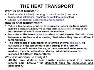
THE HEAT TRANSPORT. What is heat transfer ? Heat transfer (or heat) is energy in transit (motion) due to a temperature difference (anology current flow, mass flow) Modes : Conduction, Convection and Radiation How is heat transferred ?

THE HEAT TRANSPORT
E N D
Presentation Transcript
THE HEAT TRANSPORT What is heat transfer ? • Heat transfer (or heat) is energy in transit (motion) due to a temperature difference (anology current flow, mass flow) • Modes :Conduction, Convection and Radiation How is heat transferred ? • When a temperature gradient exists in a stationary medium, which may be a solid or a fluid, we use the termconduction to refer to the heat transfer that will occur across the medium • In contrast, the termconvectionrefers to heat transfer that will occur between a surface and a moving fluid when they are at different temperatures. • The third mode of heat transfer is termedthermal radiation. All surfaces of finite temperature emit energy in the form of electromagnetic waves. Hence, in the absence of an intervening medium, there is net heat transfer by radiation between two surfaces at different temperatures Why is it important to study it ? All the three kinds of heat transfer modes prevail in a nuclear reactor core, however the dominant ones areconduction and convection.
THE HEAT TRANSPORT(continued) Physical Origins OF Conduction Conduction may be viewed as the transfer of energy from the more energetic to the less energetic particles of a substance due to interactions between the particles. We may speak of the net transfer of energy by random molecular motion as a Diffusion of energy Examples : The exposed end of a metal spoon suddenly immersed in a cup of hot tea will eventually be warmed due to the conduction of energy through the spoon. On a winter day there is significant energy loss from a heated room to the outside air. This loss is principally due to conduction heat transfer through the wall that separates the room air from the outside air. Rate Equation for Conduction It is possible to quantify heat transfer processes in terms of appropriate rate equations.These equations may be used to compute the amount of energy being transferred per unit time. For heat conduction, the rate equation is known as Fourier’s Law. For the one dimensional plane wall shown in Figure 2, having a temperature distribution T(x), the rate equation is expressed as qx’’ = - k
THE HEAT TRANSPORT(contd) • The heat flux qx’’ (W/m2) is the heat transfer in the x direction per unit area perpendicular to the direction of transfer, and it is proportional to the temperature gradient, dT/dx, in this direction. • The proportionality constant k is a transport property known as the thermal conductivity (W/m.K) and is characteristic of the wall material. The minus sign is a consequence of the fact that heat is transferred in the direction of decreasing temperature. Under the steady state conditions shown in Figure 3, where the temperature distribution is linear, the temperature gradient may be expressed as and the heat flux is then qx’’ =
THE HEAT TRANSPORT(contd) Convection The convection heat transfer mode is comprised of two mechanisms. In Energy transfer due to random molecular motion (diffusion), there is also energy being transferred by the bulk, or macroscopic, motion of the fluid. This fluid motion is associated with the fact that, at any instant, large numbers of molecules are moving collectively or as aggregates. Such motion, in the presence of a temperature gradient, will give rise to heat transfer. Because the molecules in the aggregate retain their random motion, the total heat transfer is then due to a superposition of energy transport by the random motion of the molecules and by the bulk motion of the fluid. It is customary to use the term convection when referring to this cumulative transport and the term advection when referring to transport due to bulk fluid motion • Types of Convection • Forced Convection • Natural Convection
THE HEAT TRANSPORT(contd) Forced Convection Convection heat transfer may be classified according to the nature of the flow. We speak of forced convection when the flow is caused by external means, such as by a fan, a pump, or atmospheric winds. As an example, consider the use of a fan to provide forced convection air cooling of hot electrical components on a stack of printed circuits boards. Natural Convection In contrast, for free (or natural) convection the flow is induced by buoyancy forces that arise from density differences caused by temperature variations in the fluid. Rate Equation for Convection For convection heat transfer process, the Newton’s Law of Cooling expresses the rate equation as: q’’ = h(Ts – Tf) where q’’ is the convective heat flux (W/m2) that is proportional to the difference between the surface and fluid temperatures, Ts and Tf, respectively. The proportionality constant h (W/m2 C) is referred to as the convection heat transfer coefficient. It encompasses all the parameters that influence convection heat transfer. It particular it depends on the surface geometry, the nature of fluid motion, and an assortment of fluid thermodynamic and transport properties.
HEAT GENERATION IN REACTORS In nuclear reactors, the main source of energy is the nuclear reaction namely, Fission. A second important class, but one that produces much less energy (relative to fission) is radioactivity. In nuclear reactors fission, of a heavy nucleus of Uranium, Plutonium or Thorium splits into two or more lighter nuclei resulting in a net decrease of mass that ultimately converts into exothermic energy. • The average total energy is about 200 MeV per fission in case of 235U. • The complete fission of 1 g of 235Unuclei in a fuel element thus produces a quantity of energy equal to (Avogadro No. x 200 Mev)/U235 isotope mass = (6.0225 x 1023 x200)/235.0439 = 0.513 x 1024 Mev =2.276 x 10⁴ kW-hr =948 kW-Day =0.948 MW-Day
HEAT GENERATION IN REACTORS(Contd) Figures to remember • 200 Mev per fission • 1 g of fissionable material per day generates nearly 1 MW of energy • approximate energy consumed by normal human during daily business is 100 Watt • when we wink eye, the energy consumed is less than 1eV. Heat Generation Rate in Fuel ‘In a nuclear reactor the role of neutrons is analogous to that of oxygen in case of a coal fired plant.’ The rate of nuclear heat generation is equal to the rate of reaction producing energy times the energy per reaction. In general, the rate of any reaction between mono-energetic neutrons and the nuclei of material is given by R = . (1) Where is the macroscopic cross section, cm—1, of the reactor and the neutron flux, neutrons/s-cm2. R therefore has the units ‘reactions/s-cm3’ The energy generated in a reaction per unit time and volume is called volumetric thermal source strength, q’’’, given by q’’’ = G.R=G.. (2)
HEAT GENERATION IN REACTORS(Contd) Where G is the energy per reaction, MeV. In case of energy by fission by neutrons of a given distribution [In nuclear reactors neutrons are available with energies ranges form 17 MeV (Fast) down to 0.4 eV (Thermal)] The is the macroscopic cross sectiongiven by = N q’’’ = G N (3) where N is the density of fissionable fuel in nuclei/cm3. The value is the microscopic cross section cm2 for the fissionable fuel used and the energy distribution of the neutrons in the reactor. q’’’ has the units of Mev/s cm3 Significance For heat transfer calculations of a nuclear reactor, it is important to evaluate the volumetric thermal source strength at different positions in a reactor core before evaluating the core temperature distributions, and core heat generation and heat removal. The neutron flux is obtained from neutronic analysis/considerations
HEAT GENERATION IN REACTORS(Contd) Example Calculate the volumetric thermal source strength at a position in a reactor core in which the neutron flux is 1013. The core is loaded with a fuel having fissionable fuel density of 8.5 x 10²⁰ nuclei/cm3. The moderator temperature at the same core position is 60 oC corresponding to which the effective microscopic cross section is 400 barns. Solution N = 8.5 x 1020=400 b = 400 x 10-24 cm2 G = 180 Mev/fission Therefore volumetric source strength, q’’’ q’’’ = G. .N. = 180 x 8.5 x 1020 x 400 x 10-24 x 1013 = 6.12 x 10¹⁴ Mev/s-cm3 = 6.12 x 10¹⁴ Mev/s-cm3 x 1.602 x 10-13 w/cm3 per Mev/s-cm3 = 98.04 w/cm3 A fuel rod, having diameter and active fuel length of 3.454 and 306 cm, respectively, when placed at this location will have an average power out put of. =98.04 x x 1.7272 x 306/1000 281 kW
CORE THERMAL DESIGN • The amount of reactor power generation in a given reactor is limited by thermal rather than by nuclear considerations. The reactor core must be operated at such a power level, that with the best available heat removal system, the temperatures of the fuel and cladding anywhere in the core must not exceed safe limits. Otherwise fuel element damage might result in release of large quantities of radioactive material into the coolant, or in core fuel meltdown. • Reactor cores are usually limited by those parameters that cause the temperatures to exceed safe limits. (For KCP Reactors, Fuel Centerline and Clad Temperatures).
Peaking Factors • Radial peaking factorof a fuel rod is ratio of its power generation to the average power generated by a rod. (maximum 1.483) • In axial direction flux also varies like a ‘Cosine Shape’. Power generated from central region of fuel rod (moderated portion) is greater than its upper & lower parts. • Axial peaking factor of a fuel rod at its any location/ portion is ratio of its power or power density or flux at that location to the average power or power density or flux of same fuel rod. (maximum 1.525) Fuel centerline, fuel surface & clad surface Temperatures are maximum near central portion of fuel rod and least at ends (top/ bottom) of fuel rod. • Radial peaking factor of a fuel rod depends upon its location in core & is independent of power level or power density. Radial peaking factor of each rod in a circle (25 in KCP-3/ 4) is approximately same. • Axial peaking factor of a fuel rod does not depend upon its location in core & depends upon power level or power density. Axial peaking factors of all fuel rods in the core is approximately same.
CORE THERMAL DESIGN From now onwards procedures will be discussed for obtaining maximum temperatures (fuel, clad and coolant) in a nuclear reactor with particular emphasis to the PR100. Coolant Outlet, Maximum Clad and Fuel Centre Line Temperatures The applicable equations and correlations used for the estimation of various temperatures of interest are found below. Detailed derivation of these follow from the basic principles of heat balance. Axial Variation of Thermal Source Strength In a reactor core, the axial variation of neutron flux along the fuel element is given by (1) and so is the variation of volumetric source strength for a fuel element/rod having uniform x-section and enrichment. (2) where q’’’ and qc’’’ are the volumetric thermal source strengths at any point along the height and centre of the fuel rod, respectively.
Power Distribution (kW) in Core with All Shutoff Rods Out Reference Core at 40 MW
Axial Temperature Distribution in the Hottest Channel at 40 MWCritical Moderator Height :290 cm Coolant Flow Rate: 30 Igpm
Axial Temperature Distribution in the Hottest Channel at 48 MW
Axial Temperature Distribution (Hottest and Average Channel of KCP-III)
Criteria for Safe Operating Power Level The safe operating power level as a function of moderator height has been assessed based on the following criteria which is to be satisfied under all operating conditions i.e. overpower limiting set point of 110% and low flow set point of 90%. • The maximum temperatures at fuel centerline, fuel‑clad and clad‑coolant interfaces should remain within the following prescribed limits: • The fuel center line temperature should not exceed 668 oC in order to avoid the phase change; • The fuel surface temperature should not exceed 200 oC to prevent formation of uranium‑aluminium alloy; • The clad surface temperature should not exceed 130 oC to preclude corrosion of aluminium by coolant water. • Nucleate boiling should not commence at any point in the core • The core should have sufficient safety margins against onset of nucleate boiling and departure from nucleate boiling.
Boiling,Sub cooled,Bulk boiling,Saturation Temp. Boiling: Process in which the vapours formed with in the liquid when vapour pressure is equal to the atmospheric pressure.When temperature of fluid approached saturation temp. boiling starts. Saturation Temp: The temp. at which boiling starts. Sub cooled Nucleate Boiling: When heating surface temp. is greater that Tsat. But bulk liquid temperature is below Tsat.(small bubbles form and collapse before reaching surface temperature. Bulk Boiling: When all the liquid is at Tsat(100 oC).During phase change no increase in Temperature. Latent Heat of Vaporization: Heat supplied (at Tsat) to change the phase is called “latent heat of vaporization.
Boiling Regimes c f Surface heat flux (w/cm2) e d b a a o Tc – Tf (Clad Surface – Coolant) 0C
Boiling Regimes (Contd) • (0 to a) Natural / Forced convection heat transfer b/w clad and coolant. • (a to b) Via Natural/Forced Convection,agitation(bubble formation),subcooled nucleate boiling at ‘b’(ONB starts) bubble forms and collapse at clad surface before reaching bulk liquid.(local/sub cooled boiling) • (b to c) number of bubble formation increases,turbulent increases and surface heat flux increases. (bulk/volume boiling) • At point “C” DNB starts. • (c to d) film boiling reduces the heat transfer(partial film boiling). • (d to e) full film formation which insulate heating surface. • (e to f) heat transfer is mainly via radiation,super heated steam. Back
Accident and Transient Analysis • Accident/ Transient Analysis using Computer Code “PARET” for different PIEs: • Uncontrolled Moderator Pump up • Withdrawal of a Shutoff rod • Removal of an In Pile Experiment • Accident Drop of an Enriched Fuel Rods • Ramp Reactivity Insertion • Step Reactivity Insertions