Download
1 / 42
720 likes | 1.22k Vues
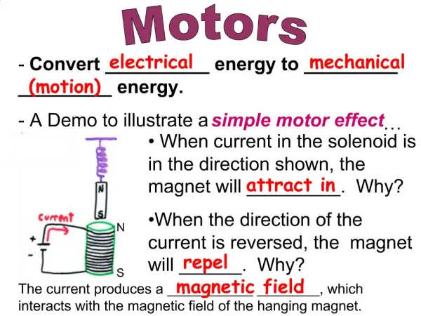
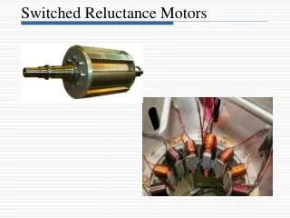
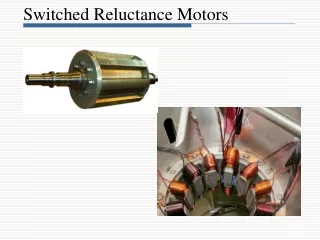
Switched Reluctance Motors. Introduction. The switched reluctance motor (SRM) is an electric motor in which torque is produced by the tendency of its moveable part to move to a position where the inductance of the excited winding is maximized .

E N D
Introduction • The switched reluctance motor (SRM) is an electric motor in which torque is produced by the tendency of its moveable part to move to a position where the inductance of the excited winding is maximized. • SRM is a type of synchronous machine. It has wound field coils of a DC motor for its stator windings and has no coils or magnets on its rotor. • It can be seen that both the stator and rotor have salient poles; hence, the machine is a doubly salient, singly excited machine.
Introduction-cont. Stator windings on diametrically opposite poles are connected in series or parallel to form one phase of the motor. Several combinations of stator and rotor poles are possible, such as 6/4 (6 stator poles and 4 rotor poles), 8/4, 10/6 etc. The configurations with higher number of stator/rotor pole combinations have less torque ripple.
SRMs Linear SRMs Rotary SRMs Axial Field Radial Field Short flux path machines: Adjacent pole windings are in series to form a phase winding Single-stack Long flux path machines: Doubly Salient with concentric windings, diametrically opposite windings are in series to form a phase Multi-stack Configuration • Initial classification is made on the basis of the nature of the motion (i.e., rotating or linear). • The linear SRMs (LSRMs) have found application in the marketplace by catering to machine tool servos. • The rotary machine-based SRM is differentiated to radial field SRM and axial field SRM by the nature of the magnetic field path as to its direction with respect to the axial length of the machine.
Configuration-cont. Radial field SRM: The magnetic field path is perpendicular to the shaft or along the radius of the cylindrical stator and rotor. Short flux path in a five-phase radial field SRM with 10/8 pole
Configuration-cont. Axial field SRM: The magnetic field path is along the axial direction. Whole motor Rotor The short magnetic flux path
Configuration-cont. LSRM: The motion of the motor is linear. Structure: A LSRM may have windings either on the stator or translator (the moving part). Fixed part is called track. Moving part is called translator. Applications: Ideal for machine tool drives Two sided LSRM with winding on the translator One side LSRM
Principle of Operation Cross sectional model of a three phase SRM, winding arrangement, and equilibrium position with phase 1 excited
Principle of Operation-cont. • Rotor rotation as switching sequence proceeds in a three phase SRM, the rotation direction is opposite to the direction of the excited phase. • The switching angle for the phase current is controlled and synchronized with the rotor position, usually by means of a shaft position sensor.
Torque Production Flux-linkage Stored field energy Magnetization curve Co-energy 0 Current i Definition of co-energy and stored field energy
Torque Production-cont. The torque production in SRM can be explained using the elementary principle of electro-mechanical energy conversion. The general expression for the torque produced by one phase at any rotor position is Where T is the torque W’is the co-energy Δ is the displacement of the rotor The constant-current constraint in the formula ensures that during such a displacement, the mechanical work done is exactly equal to the change in the co-energy.
Torque Production-cont. In a motor with no magnetic saturation, the magnetization curves would be straight lines. At any position, the co-energy and the stored magnetic energy are equal, which are given by Where L is the inductance of a exciting stator phase at a particular position. In this case the instantaneous torque can be derived as
Energy Conversion process In the real switched reluctance motor, the energy conversion process in an SRM can be evaluated using the power balance relationship. The first term represents the stator winding loss; and The second term denotes the rate of change of magnetic stored energy; The third term is the mechanical output power. The second term always exceeds the third term. The most effective use of the energy supplied is to maintain phase current constant during the positive dLph/dq slope, in which way, the second term is equal to zero
Torque Production-summary • The torque is proportional to the square of the current and hence, the current can be unipolar to produce unidirectional torque. • Since the torque is proportional to the square of the current, it has a good starting torque. • Because the stator inductance is nonlinear, a simple equivalent circuit development for SRM is not possible. • The torque characteristics of SRM are dependent on the relationship between flux linkages and rotor position as a function of current.
Equivalent Circuit An elementary equivalent circuit for the SRM can be derived neglecting the mutual inductance between the phases as following: • The first term is the resistive voltage drop • The second term is the inductive voltage drop, and • The third one is the induced emf, which can be very high at high speeds
Torque-speed Characteristics The torque-speed plane of an SRM drive can be divided into three regions: constant torque region, constant power region and constant power*speed region
Torque-speed Characteristics-cont. • Region1: The constant torque limit region is the region below the base speed ωb, which is the lowest possible speed for the motor to operate at its rated power. For the small back-emf in this region, the current can be set at any desired level by means of regulators such as hysteresis controller or voltage PWM controller. • Region2: The constant power limit region is the region where the controller maintains the torque inversely proportional to the speed. In this region, the phase excitation time falls off inversely with speed and so does the current. Because torque is roughly proportional to the square of the current, the rapid fall in torque with speed can be countered by adjusting the conduction angle qdwell. By advancing the turn-on angle to increase the conduction angle until it reaches its upper limit at speed ωp, the phase current can be increased effectively to maintain the torque production at a high level.
Torque-speed Characteristics-cont. • Region 3: In this region, the qdwell upper limit is reached when it occupies half the electrical cycle. The torque in this region is governed by natural characteristics, falling off as 1/ω2.
Power Losses Stator copper losses When consider the case where phase currents are overlapping with both the previous and succeeding phases, note that the stator copper losses at any time are the sum of the copper losses contributed by the instantaneous phase currents. The resistive losses are the result of the cumulative effect of all three currents, evaluated as follows: where Iph is the peak value of phase current, Rs is the per-phase resistance of the stator winding, Tr and Tf are the current rise and fall time, Ns and Nr are the number of stator poles and rotor poles, and ωm is the rotor speed in rad/s.
Power Losses-cont. Core losses The core losses are difficult to predict in the SRM due to the presence of flux densities with various frequencies in stator segments for these flux densities are neither pure sinusoids nor constants. The core losses consist of hysteresis and eddy current losses. The magnitude of the hysteresis losses is determined by the frequency of flux reversal and its path. To reduce the eddy current losses, the stator and rotor cores are laminated.
SRM Drive System Switched Reluctance Motor
Position Sensors Commonly used position sensors are • Phototransistors and photodiodes • Hall elements • Magnetic sensors • Pulse encoders • Variable differential transformers
Power Converters for SRM Since the torque in SRM drives is independent of the excitation current polarity, the SRM drives require only one power switch per phase winding, for example: Asymmetric bridge converter C-dump converter
Applications Flameproof drive systems for potentially explosive atmospheres Washing machine
Applications-cont. Environmentally friendly air conditioning system for passenger trains Servo systems for advanced technology weaving machine
MATLAB/SIMULINK Simulation • Library • Machines • Description
MATLAB/SIMULINK Simulation • The Switched Reluctance Motor (SRM) block represents three most common switched reluctance motors: three-phase 6/4 SRM, four-phase 8/6 SRM, five-phase 10/8 SRM, as shown in the following figure.
MATLAB/SIMULINK Simulation • The electric part of the motor is represented by a nonlinear model based on the magnetization characteristic composed of several magnetizing curves and on the torque characteristic computed from the magnetization curves. The mechanic part is represented by a state-space model based on inertia moment and viscous friction coefficient. • To be versatile, two models are implemented for the SRM block: specific and generic models. In the specific SRM model, the magnetization characteristic of the motor is provided in a lookup table. The values are obtained by experimental measurement or calculated by finite-element analysis.
MATLAB/SIMULINK Simulation • In the generic model, the magnetization characteristic is calculated using nonlinear functions and readily available parameters.
Dialog Box and Parameters • Configuration Tab
Dialog Box and Parameters • TypeSpecifies a three-phase 6/4 motor, four-phase 8/6 motor, or a five-phase 10/8 motor. • Machine modelSelect Generic model or Specific model. The Parameters tab is modified accordingly.
Dialog Box and Parameters • Parameters Tab: Generic Model
Dialog Box and Parameters • Stator resistanceThe resistance Rs (Ω) of each stator phase winding. • InertiaThe inertia momentum J (kg.m2). • FrictionThe friction coefficient B (N.m.s). • Initial speed and positionThe initial rotation speed w0 (rad/s) and initial rotor position Theta0 (rad). • Unaligned inductanceThe stator inductance when the rotor is in unaligned position Lq (H). • Aligned inductanceThe unsaturated stator inductance when the rotor is in aligned position Ld (H). • Saturated aligned inductanceThe saturated stator inductance when the rotor is in aligned position Ldsat (H). • Maximum currentThe stator maximum current Im (A). • Maximum flux linkageThe maximum flux linkage ψm (Wb or V.s) corresponding to Im.
Dialog Box and Parameters • Parameters Tab: Specific Model
Dialog Box and Parameters • Stator resistanceThe resistance Rs (Ω) of each stator phase winding. • InertiaThe inertia momentum J (kg.m2). • FrictionThe friction coefficient B (N.m.s). • Initial speedThe initial rotation speed w0 (rad/s) and initial rotor position Theta0 (rad). • Rotor angle vectorThe rotor position Θ (deg) for which the flux linkage is specified. • Stator current vectorThe stator current Is (A) for which the flux linkage is specified. • Magnetization characteristicThe 2-D lookup table containing the flux linkage as a function of stator current and rotor position.
Dialog Box and Parameters • Advanced Tab
Dialog Box and Parameters • Plot magnetization curvesIf selected, the mask plots the magnetization curves corresponding to the lookup table provided. The magnetization curves represent the machine flux linkage versus the stator current with the rotor position as a parameter. • Sample time (-1 for inherited)Specifies the sample time used by the block. To inherit the sample time specified in the Powergui block, set this parameter to -1.
Inputs and Outputs • TL: The block input is the mechanical load torque (in N.m). TL is positive in motor operation and negative in generator operation. • M: The block output m is a vector containing several signals. You can demultiplex these signals by using the Bus Selector block from Simulink library.
Example • The power_SwitchedReluctanceMotor demo illustrates the simulation of the Switched Reluctance Motor.
Phase Inductance and Current Ideal Waveforms • To develop positive torque, the currents in the phases of a SRM must be synchronized to the rotor position. The following figure shows the ideal waveforms (Phase A inductance and current) in a 6/4 SRM. Turn-on and turn-off angles refer to the rotor position where the converter's power switch is turned on and turned off, respectively.