Download
1 / 23
270 likes | 1.08k Vues
MODELLING & torque pulsation reduction OF Switched reluctance motor. G.PRASHANT Edited By Sarath S Nair www.technologyfuturae.com. contents. INTRODUCTION CONSTRUCTIONAL FEATURES OPERATING PRINCIPLE SYSTEM DESCRIPTION AND MODELING STUDY OF TORQUE PULSATION ADVANTAGES APPLICATIONS

E N D
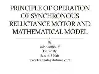
www.technologyfuturae.com MODELLING & torque pulsation reduction OF Switched reluctance motor G.PRASHANT Edited By Sarath S Nair www.technologyfuturae.com
www.technologyfuturae.com contents • INTRODUCTION • CONSTRUCTIONAL FEATURES • OPERATING PRINCIPLE • SYSTEM DESCRIPTION AND MODELING • STUDY OF TORQUE PULSATION • ADVANTAGES • APPLICATIONS • CONCLUSION
www.technologyfuturae.com INTRODUCTION • The name switched reluctance describes two features : a) switched- the m/c must be operated in continuous switching mode b) reluctance- it is the true reluctance m/c in the sense that both stator and rotor have variable reluctance magnetic circuit • It is a double salient machine. • It illuminates permanent magnet, brushes & commutators. • Due to inherent simplicity it has reliable and low-cost variable-speed drive
www.technologyfuturae.com Constructional • Stator consist of steel laminations forming the salient pole • With no rotor winding,the rotor is basically a piece of steel (and laminations) shaped to form salient poles. Hence no Cu loss in rotor winding • It is the only motor with salient poles in rotor & stator.
www.technologyfuturae.com 6/4 switched reluctance machine with one phase excited
www.technologyfuturae.com Operating principle • One phase of stator is energized at a time by dc voltage pulses. • The rotor experiences a torque and moves to a position to align with stator pole so that the reluctance is minimum & inductance is maximum. • If rotor continues past the aligned position braking torque is produced • Current is switched off to remove this condition of breaking torque
www.technologyfuturae.com MATHEMATICAL MODEL OF SR MOTOR • The motor is single phase excited ; that is it carries one winding on the stator. • The excited winding is wound on the stator & the rotor is free to rotate.
www.technologyfuturae.com SYSTEM DESCRIPTION
www.technologyfuturae.com Contd.. • System consists of four major parts- motor, current-regulated converter , controller and sensors • Controller computes the error and outputs the current command to the converter • Sensors used are current and speed sensors • System consists of current and speed loop only
www.technologyfuturae.com MODELING • Stationary frame model • Self-inductance of the motor is related to the position of rotor • Assuming self-inductance of each phase isn’t related to its phase current • The flux linkage of the rotor can be expressed as • Where j=a,b,c
www.technologyfuturae.com Contd.. • The dynamic equation of each phase voltage is • And the torque equation is given as
www.technologyfuturae.com Contd… • Synchronous frame model the transformation from abc to dq axis can be expressed as
www.technologyfuturae.com Contd.. • The synchronous d-q axis voltage equation are • The torque equation is
www.technologyfuturae.com TORQUE PULSATION • Major disadvantage of SRM is that its torque pulsation is larger than other machines • Self-inductance’s value changes according to the position of stator and rotor • From the self-inductance waveform the current control commands can be obtained for producing maximum and minimum torque
www.technologyfuturae.com Contd.. • The real self-inductance can be expressed as • Where j=a,b,c. • ϴe=Nrϴrm • ϴrm= mechanical shaft angle
www.technologyfuturae.com Contd.. • Neglecting the harmonic components and hence considerring only the fundamental components • where L’j is the values of the self-inductances in the abc stationary frame. • its approximate value in dq synchronous frame is
www.technologyfuturae.com • The equivalent value obtained is
www.technologyfuturae.com ADVANTAGES • Performance- much greater torque output • Low cost- low manufacturing cost, low material & maintenance cost. It does not use magnets. • Cooling- most of the heat is generated in which is relatively easy to cool.
www.technologyfuturae.com applications • SRMs are used in some washing machine designs. • SRM drives are ideal for aircraft applications such as a jet engine starter motor generator. • Bearingless switched reluctance motor for all electric propulsion system
www.technologyfuturae.com summary • The construction, operating principle & key features of switched reluctance motor are explained. • The mathematical model & flux linkage characteristics are analysed. • The torque pulsation problem of the switch reluctance motor was also discussed
www.technologyfuturae.com references [1] Miller, 7: J. E., Switched Reluctance Motors and Their Control, Clarendon Press, Oxford, 1992. [2] R. Krishnan, Switched Reluctance Motor Drives: Modelling, Simulation, Analysis, Design, and Applications, CRC Press, 2001 [3] R. S. Wallace, D. G, Taylor, "A balanced commutator for switched reluctance motors to reduce torque ripple," IEEE Trans. Pow. Electron., vol. PE-7, 110. 4, pp. 617-626, Oct. 1992. [4] D. S. Reay, M. M. Moud, T. C. Green, and B. W.Williams, "Switched reluctance motor control via fuzzy adaptive systems," IEEE Control Systemsvol. 15, no. 3, pp. 8-15, June 1995.
Technical Presentations, Research Reviews, New designs & Developments TechnologyFuturae Log On to www.technologyfuturae.com
www.technologyfuturae.com THANK YOU