Download
1 / 23
230 likes | 427 Vues
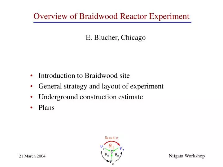
Overview of Braidwood Reactor Experiment. E. Blucher, Chicago. Introduction to Braidwood site General strategy and layout of experiment Underground construction estimate Plans. Niigata Workshop. Midwest Collaboration. ANL: Maury Goodman, David Reyna

E N D
Overview of Braidwood Reactor Experiment E. Blucher, Chicago • Introduction to Braidwood site • General strategy and layout of experiment • Underground construction estimate • Plans Niigata Workshop
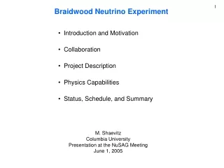
Midwest Collaboration ANL: Maury Goodman, David Reyna Chicago: Erin Abouzaid, Kelby Anderson, Ed Blucher, Jim Pilcher, Matt Worcester Columbia: Janet Conrad, Jon Link, Mike Shaevitz FNAL: Larry Bartoszek, Dave Finley, Hans Jostlein, Chris Laughton, Ray Stefanski Kansas: Tim Bolton, Noel Stanton Oxford: Steve Biller, Nick Jelley Pittsburgh: Donna Naples, Vittorio Paolone Texas: Josh Klein
We considered several sites in Illinois (Braidwood, Byron, Lasalle) and Kansas (Wolf Creek). • We have focused on the Braidwood site managed by Exelon Nuclear. • Braidwood: • 23.6 GW reactors – • 7.17 GW (thermal) maximum power • Efficient operation: 90% capacity • factor over last several years.
Braidwood site • Features of Braidwood site: • 23.6 GW reactors – 7.17 GW maximum power • Flat: flexibility, equal overburden at near and far sites, surface • transportation of detectors • Favorable geology (dolomitic limestone): good for excavation, • low radioactivity (order of magnitude lower U, Th than granite)
Physics Goals of Experiment I. sin22~0.01: If sin22 < 0.01, it will be difficult for long- baseline “superbeam” experiments to investigate mass hierarchy and CP violation. Reactor experiment with sensitivity of 0.01 will indicate scale of future experiments needed to make progress. If sin22 is relatively large (e.g. observable by Double Chooz), a precision measurement will be needed to combine with accelerator experiments. II. sin2W: If possible, maintain design that will allow measurement of sin2W using antineutrino-electron elastic scattering in near detector. Ideally, near detector should be close to reactor, deep, and have the same overburden as far detector (to allow measurement of environmental backgrounds using far detector). See talk by M. Shaevitz this afternoon.
General Strategy of Experiment Detector Concept ~200 m ~1600 m • 1 near detector and 2 far detectors (at oscillation maximum) • 6.5 m diameter spherical detectors with 3 zones (Gd-loaded scint.) • 25-50 ton fid. mass per detector, depending on required buffer regions • Movable detectors with surface transport for cross-calibration; vertical • shaft access to detector halls • Full detector construction above ground • Near and far detectors at same depth of 450 mwe (contingent • on bore holes) • Near detector at ~200 m security perimeter (L~270 m); far detectors • at ~1800 m
3-zone Gd-based Detector I. Gd-loaded liquid scintillator II. catcher: liquid scintillator (no Gd) III. Non-scintillating buffer Two examples: PMTs I 6.5 m II III • R=2.4 m, m=50 tons • R=2.7 m • R=3.25 m • R=1.9 m, m=25 tons • R=2.4 m • R=3.25 m Total detector mass ~150 tons
Detector Optimization We’ve developed a hit-level Monte Carlo for initial design studies. In parallel, we’re developing a Geant-4 based detector model. • Currently studying detector • optimization: • required buffer thicknesses • active and passive shielding
Relative Acceptance Strategy • Establish relative acceptances as well as possible without detector movement – careful detector construction, radioactive sources, reactor interactions, cosmics, etc. n+Gd For example: n+H • Measure relative acceptances by cross-calibrating detectors • at near detector location:surface movement of detectors
Relatively flat terrain allows • “inexpensive” movement • of detectors on surface. • Many crane options with adequate capacity E.g., 750-ton capacity crawler crane performing test lift of 750 tons • Surface movement either with • multi-axle “truck” on gravel • road or with surface rail system • (depends on acceptable stresses)
Example of transporter moving 550 ton drum from ship to crane hook
Conceptual Mechanical Design • Design issues: • Support for concentric acrylic vessels • Integration of source calibration system with vessel support • Integration of detector design with surface movement (i.e., • what is maximum safe instantaneous acceleration?) • Engineering of active and passive veto system
Underground Construction Estimate • A detailed estimate of cost and schedule for underground construction • at the Braidwood site was recently performed by Hilton and • Associates, Inc. (tunnel cost estimating consultants). • Complete estimate of costs associated with underground facility; • including all civil construction, underground outfitting (pumps, • elevators, ventilation, etc.); even includes cost associated with • decommissioning shafts at end of experiment. • Does not include permanent surface buildings or detectors. • Components of cost separated in enough detail to allow scaling • of costs with changes in design.
Braidwood Site Reactors Controlled perimeter
Layout for underground construction estimate Reactors Far shaft Near shaft Near detect. hall Braidwood
Near & Far Shaft Layouts Tunnel cross section Not to Scale
Two Styles of Detector Halls Near hall: Detector hall cross section 2 m 12 14 32 m Far hall: 12 m 12 14 15 m 12 m
Two Styles of Detector Halls Near hall: Detector hall will accommodate active and passive shielding 12 14 32 m tracking Far hall: passive shielding 12 14 15 m 12 m
Layout used for underground construction estimate: • 300 mwe, two shafts, different detector hall designs, 300m tunnel • Cost: $35 million; Time: 39 months with sequential construction. • Revised layout: • Increase depth to 450 mwe (160 m rock + 20 m soil) contingent • on bore hole results • Site near detector shaft to shorten or eliminate tunnel stub • Use near hall design at both near and far sites • Cost: $25-35 million • Time: ~36 months with sequential construction of near and far • sites; < 2 years with simultaneous construction of sites.
Revised Layout Reactors Far shaft Site near shaft to shorten or eliminate tunnel Braidwood
Conclusions • Braidwood site appears very attractive • High power reactor with cooperative management • Can use vertical shafts to reach necessary depth • Surface movement of detectors seems technically feasible. • Settle surface layout (location of shafts, infrastructure for detector movement) in consultation with Exelon. • Drill bore holes to full depth at both shaft positions: provides info about geology, radioactivity, density; will reduce contingency required for construction. • Optimize detector design for acceptance uncertainty and background rejection (buffer regions, calibration system, active and passive shielding, etc.) Short-term Plans: