IceTop functions
IceTop functions. A 3-dimensional air shower array for Veto (i.e. tagging downward events) Calibration Primary composition from PeV to EeV Calibration, composition analyses similar to SPASE-AMANDA but 5000 x larger acceptance wider energy range, better resolution

IceTop functions
E N D
Presentation Transcript
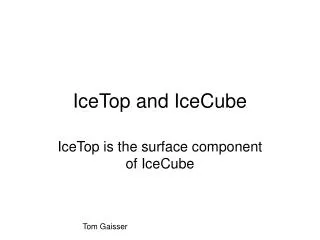
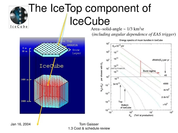
IceTop functions • A 3-dimensional air shower array for • Veto (i.e. tagging downward events) • Calibration • Primary composition from PeV to EeV • Calibration, composition analyses similar to SPASE-AMANDA but • 5000 x larger acceptance • wider energy range, better resolution • IceTop at high altitude (700 g/cm2) • 125 m spacing between IceTop stations • Ethreshold ~ 300 TeV for > 4 stations in coincidence • Useful rate to EeV T. Gaisser, L3 Lead for 1.3.2 IceTop
IceTop + IceCube: 1/3 km2 sr Coverage to EeV energy T. Gaisser, L3 Lead for 1.3.2 IceTop
Veto, Calibration, Survey • Veto • Vetos all downward events E > 300 TeV with trajectories inside IceTop • Vetos larger events falling outside • Tags 5% of m background in IceCube for study via ~3 TeV showers hitting stations • Calibration of angular resolution with tagged m bundles • Muon survey of IceCube T. Gaisser, L3 Lead for 1.3.2 IceTop
Cosmic-ray physics • IceTop EAS threshold ~ 300 TeV • Knee of spectrum ~ 3 PeV • Transition to extra-galactic CR may be below 1 EeV (HiRes, AGASA) • IceTop – IceCube coincidences • Measure spectrum, composition • Locate transition to extragalactic CR • Normalize potential extragalactic sources of high-energy neutrinos T. Gaisser, L3 Lead for 1.3.2 IceTop
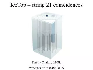
Showers triggering 4 stations give ~300 TeV threshold for EAS array Large showers with E ~ 100-1000 PeV will clarify transition from galactic to extra-galactic cosmic rays. Small showers (2-10 TeV) associated with the dominant m background in the deep detector are detected as 2-tank coincidences at a station. Detection efficiency ~ 5% provides large sample to study this background. IceTop: 80-station, km2 EAS array with 125 m spacing T. Gaisser, L3 Lead for 1.3.2 IceTop
Incident cosmic-ray nucleus n Penetrating muon bundle in shower core EeV n Detection in IceCubewith shower background m Threshold ~ 1018 eV to veto this background Potential to reject this background for EeV neutrinos by detecting the fringe of coincident horizontal air shower in an array of water Cherenkov detectors (cf. Ave et al., PRL 85 (2000) 2244, analysis of Haverah Park) T. Gaisser, L3 Lead for 1.3.2 IceTop
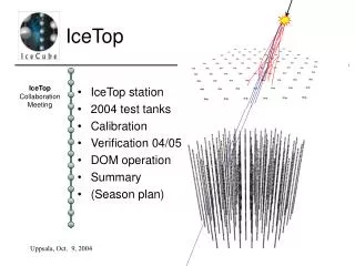
0.9 m 2 m IceTop Detector T. Gaisser, L3 Lead for 1.3.2 IceTop
IceTop station • Two Ice Tanks 3.1 m2 x 1 m deep (a la Haverah, Auger) • Integrated with IceCube: same hardware, software • Coincidence between tanks = potential air shower • Signal in single tank = potential muon • Significant area for horizontal muons • Low Gain/High Gain operation to achieve dynamic range T. Gaisser, L3 Lead for 1.3.2 IceTop
Technical requirements • IceTop station must distinguish • Random particles hitting one tank • Small showers near one station • Larger showers (4+ stations hit) • Implications for DAQ • Detector response • Integrated signal = energy deposited independent of location in tank • Time of 1st particle to < 10 ns • Implications for ice quality, tank lining T. Gaisser, L3 Lead for 1.3.2 IceTop
DAQ design goals • Feature recognition • Low-gain / high-gain • Local coincidence • Horizontal showers • Calibration mode T. Gaisser, L3 Lead for 1.3.2 IceTop
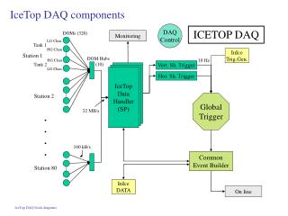
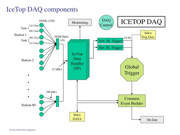
Common Event Builder IceTop DAQ components Monitoring DAQ Control ICETOP DAQ DOMs (320) LG Chan. Tank 1 InIce Trig.Gen. Vert. Sh. Trigger HG Chan Station 1 DOM Hubs (10) Hor. Sh. Trigger 10 Hz HG Chan Tank 2 IceTop Data Handler LG Chan IceTop Data Handler IceTop Data Handler (SP) Station 2 Global Trigger 32 MB/s . . . . 100 kB/s Station 80 On line InIce DATA T. Gaisser, L3 Lead for 1.3.2 IceTop
IDH and Trigger DAQ Control Monitoring Time Correction (IceTop Data Handler) Time Control Separate Monitor Data In-Ice Trigger Create stream for “station hits” Create stream for “tank hits” Shower Trigger Trap calibration data Horiz. Shower Trigger Hubs IceTop Data Buffer Global Trigger Post trigger data retrieval Common Event Builder Online T. Gaisser, L3 Lead for 1.3.2 IceTop
Detector design goals • Primary: Produce blocks of clear ice approximately two meters in diameter by one meter deep. Each block is to be viewed by two optical detectors (DOM), which are to be “frozen in” to the ice. • Secondary: • Bottom and sides of the block of ice must be covered with a diffuse, highly reflective material. • Entire assembly must be light tight. • The entire assembly must be insulated to an R value of TBD to • Minimize the amplitude and suddenness of temperature variations • Limit cracking of the ice • Meet environmental constraints of the DOM. T. Gaisser, L3 Lead for 1.3.2 IceTop
Detector construction plan • Freezing based on natural ice growth on lakes. • Clear ice is produced by a method known in the materials industry as “zone refining” which exploits the tendency of the crystal forming from the liquid phase to exclude impurities that concentrate in the remaining liquid. • In a lake, the “impurities” (which include the oxygen fish need to survive) are diluted in the large volume of lake water under the ice. • Top-down freeze allows accurate placement and “freezing-in” of DOMs at the outset • Technical issues to be faced at Pole all derive from the need to conduct the freeze in a volume of water comparable to that of the end product. • Remove expansion water as ice forms • Keep dissolved air below saturation to avoid bubbles T. Gaisser, L3 Lead for 1.3.2 IceTop
Status of detector development • 2000-01: small tank at Pole • Pressure relief via heated rod • No degassing, no insulation • 2001-02: full-size tank at Pole • Pressure relief via heated pipe • No degassing, no insulation. Freeze-time 28 days • 2002-03: freeze 2 full-size tanks in commercial freezer in Delaware, one froze from top down, one from bottom up • Both methods work • Top-down requires cooling from bottom, DOMs freeze in at end • Bottom-up requires degassing, pressure relief; DOMs freeze in initially, bottom can be closed from beginning • 2003-04: freeze two full-size test tanks at Pole • Insulated tanks assure uniform, flat freeze front, additional protection from thermal cycling. • Achieve good ice quality but • Freeze-time too long • 2003… Construction of test station in lab for calibration, testing T. Gaisser, L3 Lead for 1.3.2 IceTop
2001 test tank • Viewed by 2 AMANDA analog OMs • Cloudy ice but reasonable signals • Currently taking data for comparison with station in lab T. Gaisser, L3 Lead for 1.3.2 IceTop
Design of prototype tanks; 8 to be deployed in 04/05 with 1st 4 strings Sunshade support* Support structure for DOMS and cover Freeze-control box* DOM Insulated tank Pressure relief system Pallet *Removed after freeze T. Gaisser, L3 Lead for 1.3.2 IceTop
a) Before filling tank Degasser unit Dual unit: circulating pumps (black), filters (white) millipore degassers (outer units – connected to Vacuum ballast tank in freeze control box). Only one system at a time in operation. b) Near end of freeze under 85 cm ice T. Gaisser, L3 Lead for 1.3.2 IceTop
Current test season at Pole • Tank10 (1 m deep) • Filled Nov 22, 2003 • 20 minutes to fill • < 10 RPSC man hours for transport and filling • Tank09 ( 0.9 m ) • Filled Nov 26, 2003 T. Gaisser, L3 Lead for 1.3.2 IceTop
Cable runs looking toward MAPO away from SPASE Tank10 is on the right, Tank09 on the left. Power cable is on the left. There are 5 cables on the right: 2 freeze-control cables, two twisted quads for DOMS, and Stoyan’s cable to read temperatures during the winter. The latter is somewhat thicker than the other four. T. Gaisser, L3 Lead for 1.3.2 IceTop
Tanks closed Jan 23-26 Tank10 during freeze and after closing b) Jan 23 after closing, tent used as outer cover over black vinyl sheeting a) Dec 6 during freeze (cover used as extra sun shade) T. Gaisser, L3 Lead for 1.3.2 IceTop
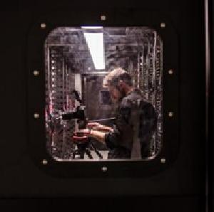
4 IceCube DOMs now running From: SMTP%"john.kelley@usap.gov" 15-JAN-2004 15:56:19.45 To: icecube-c@ssec.wisc.edu Subj: First Four IceCube DOMs Deployed I'm pleased to report that the first four IceCube digital optical modules have been successfully deployed at the pole. They are currently frozen into two IceTop surface tanks, located near the SPASE building. The DOMs are operating normally, and we are looking forward to dark-adapting the tanks and taking real data. John Kelley, UW-Madison ATWD waveforms in “scarface” --Serap Tilav, Jan 27 DOM frozen in place, Jan 15 T. Gaisser, L3 Lead for 1.3.2 IceTop
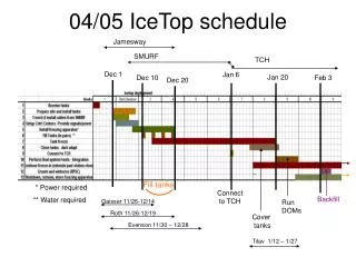
Schedule for tanks PY3 PY4 PY5 PY6 PY7 PY8 Strings deployed 4 12 16 18 18 12 Tanks Deployed: 8 24 32 36 36 24 Manufactured: 8 24 32 96 (accel) Freeze units (*) 8 (+2?) 16 (+2?) 12 0 manufctd (accel) Assumes each freeze unit reused up to 5 times. (add extras ?) T. Gaisser, L3 Lead for 1.3.2 IceTop
Schedule Milestones • Delivery of equipment for 03/04 deployment: 11/3/03 • Post-deployment meeting: 3/27/04 • Production readiness review for 8 prototype tanks: 6/15/04 • Post-deployment meeting: 4/1/05 • Second production readiness review 8/1/05 • Initial In-Ice, IceTop Data System Integration • Final Production readiness review 6/1/07 T. Gaisser, L3 Lead for 1.3.2 IceTop
Vertical m (defined by m-telescope) Data with test-tank setup at UD in water. (Large negative amplitudes on left.) In-tank coincidence (defined by 2 OMs) broadened m peak + low energy e-m background Muon self-calibration procedure • Take in-tank coincidence data for each tank for commissioning • Compare to lab template (in water) • Interpret deltas with simulations • Fix parameters for interpretation of signals • Add to data base T. Gaisser, L3 Lead for 1.3.2 IceTop
Initial calibration with SPASE • SPASE: 30 m gridthreshold ~ 20 TeV • Intermediate between 2-10 TeV of 2-tank IceTop station coincidence and 300 TeV IceTop array threshold • Important energy region for background in IceCube (small showers with 2-3 muons) • Provides tagged muon calibration and survey of first IceTop strings • Provides calibration of IceTop tanks • Sees IceCube strings from larger angle T. Gaisser, L3 Lead for 1.3.2 IceTop
Hardware (capital) costs • Capital • Tanks: 160 @ $6037 = $965,920 • Frz units: 36 @ $6002 = 216,072 • O’flow units 36 @ $ 561 = 20,196 • Sunshade 36 @ $1922 = 69,129 • Misc Tank Equip 38,550 • Test station Equip (inc. $45K at UWRF) 75,000 • 4 test station tanks + ancillary equip 60,000 • Computer cluster 180,000 • Total capital $1,564,867 (+$60K) T. Gaisser, L3 Lead for 1.3.2 IceTop
Materials & supplies (inc shipping)+ travel (both unburdened) • 1.3.2.1 Tanks $ 18,850 • (not enough for shipping) • 1.3.2.4.1 (Test stations) 31,000 • 1.3.2.4.3 127,750 • DAQ computers 27,000 move half to 1.3.2.1 • Misc hardware 100,750 move to 1.3.2.4.1 • 1.3.2.5 -000- • 1.3.2.6 48,000 • (replacement work stns) • Total M & S $225,600 • Travel $549,000 T. Gaisser, L3 Lead for 1.3.2 IceTop
Labor Costs • FTE years (by institution for total project) UD: 34.3, UW: 3.5, LBNL: 0.7, UWRF: 3.6 • By Individuals involved part-time Scientists: UD:13 UW: 1 LBNL: 0 UWRF: 2 Engrs, techs: UD: 5 UW: 1 LBNL: 2 • Labor cost by Project year (burdened, $ M) PY 3 4 5 6 7 8 1.22 1.27 1.13 0.91 0.56. 0.44 • Labor cost by WBS element ($ M) Tanks: $1.18 Cables: $0.30 DOMs: $0.22 Engineering resources: $1.32 Detector Simulations: $1.02 DAQ: $0.56 SPASE: $0.43 Management: $0.50 • Total Labor cost for 1.3.2: $5.53 M T. Gaisser, L3 Lead for 1.3.2 IceTop
Staffing Plan • FTE per project year • PY3: 7.5 8.8 • Hire technician starting June 1 • Part-time post-doc starting Sept 1 • PY4: 8.8 9.4 • Hire Junior faculty member PY5, 6 7 8 8.3 6.9 4.4 3.8 T. Gaisser, L3 Lead for 1.3.2 IceTop
Issues/Risks • First priority: speed up freeze time • Redesign of sunshade underway • Engineering study to reduce insulation • Aggressive hardware schedule: • 8, 24, 32, 96 tanks in successive years • How to implement transition of effort to data handling, detector verification (and operations) as construction progresses T. Gaisser, L3 Lead for 1.3.2 IceTop
Summary • IceTop provides valuable calibration, survey and veto capabilities for IceCube. • The possibility of a surface array over a n-telescope is unique to IceCube. • The result is a kilometer-scale, three-dimensional air shower array, • A novel tool for cosmic-ray physics to EeV energies with likelihood of significant discoveries related to neutrino astronomy T. Gaisser, L3 Lead for 1.3.2 IceTop