Innovative Conceptual Design for IceTank Development at CRREL
This presentation outlines the conceptual design and development of an IceTank at CRREL, aiming to produce large blocks of clear ice (2m diameter x 1m deep) integrated with optical detectors. It addresses key objectives such as maintaining insulation, optical quality, and minimizing temperature variations and cracking. The new design introduces a more effective pressure relief system and uses permeable membranes for water degassing, ultimately targeting the production of high-quality ice while overcoming previous technical challenges. Results from testing indicate significant improvements in ice clarity and structural integrity.


Innovative Conceptual Design for IceTank Development at CRREL
E N D
Presentation Transcript
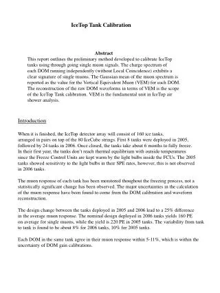
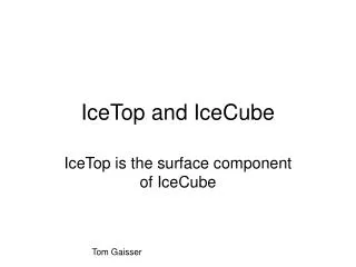
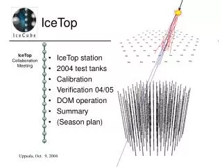
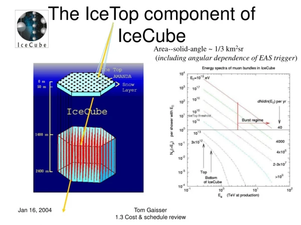
IceTop Tank Development CRREL Conceptual Design Presentation Paul Evenson University of Delaware
Objectives • Primary: Produce blocks of clear ice approximately two meters in diameter by one meter deep. Each block is to be viewed by two optical detectors (DOM), which are to be “frozen in” to the ice. • Secondary: • Bottom and sides of the block of ice must be covered with a diffuse, highly reflective material. Pending further specification, the objective is to duplicate the performance of the Auger tanks. • Top of the ice must be covered with optically absorbing material. • Entire assembly must be light tight. • The entire assembly must be insulated to an R value of TBD. • Minimize the amplitude and suddenness of temperature variations • Limit cracking of the ice • Meet environmental constraints of the DOM. • Specifications for insulation have not been established. Therefore the production method must allow for an arbitrary (large) R value on all surfaces.
Approach • Based on natural ice growth on lakes. • Clear ice is produced by a method known in the materials industry as “zone refining” which exploits the tendency of the crystal forming from the liquid phase to exclude impurities that concentrate in the remaining liquid. • In a lake, the “impurities” (which include the oxygen fish need to survive) are diluted in the large volume of lake water under the ice. • Technical issues to be faced at Pole all derive from the need to conduct the freeze in a volume of water comparable to that of the end product.
2000-2001 at Pole • Pressure was relieved by means of a heated rod that was slowly raised as water froze in from the sides and bottom • A large crack developed from the poorly relieved pressure. • Optical signals were large enough to be useful.
2001-2002 at Pole • Demonstrated a workable pressure relief system. • Took 28 days to freeze. • Pressure relief system intruded into the prime optical space of the tank. • Quality of the ice was better, with no large cracks • Ice still quite cloudy due to the inclusion of gases dissolved in the water prior to freezing. • Once a plug of ice forms in the top of the tank, it cuts off any route for dissolved gases to escape to the atmosphere.
New Conceptual Design • Pressure relief route changed from a tube inserted from the top of the tank to a pipe entering the tank at the bottom. • Water continuously withdrawn from the relief pipe at the bottom of the tank, run through a degassing device, and reintroduced through a second pipe at the bottom of the tank. • Small scale tests demonstrated that essentially perfect blocks of ice could be produced in this way.
Wilmington Test Objective • Primary issue: Is processing the water only at the bottom of a large tank sufficient to keep the concentration of dissolved air at the freezing front at an acceptable level? • Diffusion rate of air in still water is far too slow to permit a freeze in a reasonable amount of time. • Our primary objective in this test was to explore the use of thermal instability to achieve the required mixing, and thereby to avoid the need for a large mixing pump, either inside or outside the tank.
Degassing Principle There are three commonly used methods of degassing water: heating, mechanical agitation, and permeable membranes. We elected to use the permeable membrane approach, primarily because it is the only one that has a completely closed circuit for the water being treated.
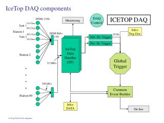
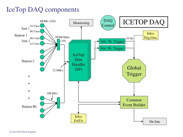
System Components • Degasser • Dissolved Oxygen Sensor • Insulation • Main Circulating Pump • Inlet Temperature Control • Temperature Sensors • Ice Quality Monitors
Bad News and Good News • Bad: Component failure let large air bubbles in when freeze was 2/3 complete. • Good: You are viewing the bubbles through two feet of ice!
In Situ Repair The tank proved to be remarkably robust, in that after correcting the problems that led to the introduction of the air we raised the inlet temperature and were able to melt back the surface of the ice to free the bubbles, which then began to dissolve into the degassed water.
Dissolved Nitrogen • Slow dissolution of bubbles indicates high gas content even with low DO • Syringe assay confirms this • Probably DN due to a small, chronic air leak
Technical Results (I) • The system works under a wide variety of input temperatures and flow rates. The concern that we might have to maintain a delicately tuned thermal gradient in the tank was unfounded. • The chiller in the inlet water temperature controller failed. Since the more important finding is that the chiller is unnecessary we have not spent a lot of time analyzing the failure mode. • One consistent feature of the ice is the presence of occasional strings of barely visible defects the ice. Material (presumably mineral deposits) forms on the ice surface, and “surfs” on the advancing ice front. Such deposits may be serving as nucleation sites for trains of bubbles which do freeze into the ice. • Using the circulating pump to run the degasser as well resulted in a large negative pressure in significant parts of the plumbing, and thus resulted in sensitivity to small air leaks. The final system must either be more leak-tight or run at a lower negative pressure. • Any air leak invalidates measurements of dissolved oxygen as a proxy for total dissolved gas, so we must have a reliable way to monitor total dissolved gas in the tanks. • The Tyvek “tank liner” did not properly conform to the tank walls. Water got behind it making the fiducial volume uncertain.
Technical Results (II) • The pressure drop in the relief line depends too much on the flow rate. If a common relief and flow line is used, it must be sized so as to eliminate this dependence. Otherwise a third line for pressure balancing operations should be used. • By warming the inlet water it is possible “melt back” the ice so as to repair flaws. • Contaminants in the water precipitate out, primarily onto the bottom of the tank. However a fine residue is also accumulating in the degasser. Some kind of inlet filter on the degasser is probably a good idea. • There is almost certainly going to be some cloudy ice at the bottom of the tank. We may work to minimize it or control it, but it is likely to be there. • Pole is colder than the Port freezer, so issues of tank freeze rate could not be specifically addressed. • Pole is at a much higher altitude than Wilmington, so the behavior of the degasser at high altitude must still be investigated.
Other Issues (I) • Will the flow rate of a metering pump alone will be sufficient or is a separate circulating pump needed? • Should we replace the continuously running degasser vacuum pump with a ballast tank and occasional-run pump to save power? • Can we live with the precipitation of contaminants expected from South Pole water? Is it necessary to treat the water? • What is the best material to cover the top of the tank? [The Auger tank liner looks like a good candidate. It is black on one side, white on the other, and waterproof. So it can clearly be made to “float” on the tank with the black side down.] • Can we stop degassing at a predictable point so that a reproducible layer of bubbly ice forms to serve as the bottom reflector and hide contaminants? • Should the ability to “melt back” be a standard feature of the system, or should we have separate “repair kits” to fix problems that might develop in individual tanks. • What is the best way to package a degassing station?
Other Issues (II) • Tank material. Assuming that some bubbly ice on the bottom is tolerable there are few constraints on the tank itself, so we could in fact now proceed to get the tanks into the “pipeline” for the eventual deployment. • Tank liner. It turns out that we were not testing the tank liner developed for Auger. From what we now understand, the Auger material seems to have better properties. The samples that we have of the supposed Auger material look waterproof and opaque as advertised. The reflective surface is however somewhat gray in overall appearance. We very much need a tank model to evaluate the possible need for a better reflector. • Water quality. A process must be put in place to assure that the water delivered to the tank is up to the specification, whatever that is. If major treatment is required, that should be probably be done at the source. • Insulation. Rigid foam insulation will be required beneath the tanks to support their weight without compressing the insulation, but snow fence reinforced fiberglass is adequate for the sides and tops.
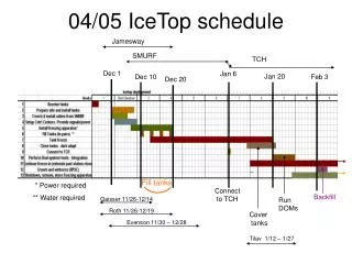
Annual Schedule • A deployment rate of two per day seems realistic. • Complete initial deployment in (about) 15 days, so as to leave 40 days for the last deployed tank to freeze under supervision. • We would need at least 32 degassers • Plan on acquiring 35 so that we will have some spares and can accommodate a “melt back” on some of the tanks to repair flaws
Deployment Plan • The deployment of each tank can be separated into four operations, allowing crews to work in parallel by having several installations in progress at once. The operations are: • Site preparation. Locate the position of the tanks and trench out the snow. • Tank placement. Place the sub-tank insulation on the snow, and put the tank onto it. Put the snow fence insulation around it. Connect the degasser unit. • Water Preparation. Fill the transport tank with water at the station. Filter, deionize, and raise the water temperature to 20 degrees C in this process. • Fill the tank. Install the floating cover. Start the degasser. Position the DOMs (which presumably also just float in their insulated jackets.
2003-2004 Objectives • Verify basic freeze technique under Pole conditions. • Leave a prototype station, possibly instrumented with DOMs
2003-2004 Tasks • The main freeze task itself: Produce blocks of ice near the current test tanks, instrumented with PMT that can be used with the multi-channel scope. • Water supply: Develop a method to deliver 1000 gallons of filtered (spec TBD), deionized (spec TBD) water at 20 degrees C per day to a location anywhere within the IceCube "footprint". One delivery per day is the required rate. • Power supply: Develop a method to provide 100 watts (average) of uninterrupted power at any location within the IceCube footprint. An interruption of more than TBD (but probably something like 5-10) minutes over a 20 day operating period must be considered a mission critical failure. • DOM test tank: Provide a full scale, water filled test tank near a CONUS laboratory for development of DOM firmware and DAQ systems. • Tank liner: Produce a waterproof, light-tight tank liner with TBD optical properties internally. This must include a floating cover for the top of the tank which is highly reflective on its outer surface, or is capable of supporting a reflective cover. • DOM insulation: Develop an insulated housing for the DOM that will allow it to be positioned at the ice surface with the proper insertion dimension and orientation. • Optimum degassing system: Some investigation, and possible testing, of a system suitable for purchase (or construction) of a reliable system in production quantities. • Reliability Targets: Develop a plan specifying how many of the tanks (if any) are permitted to have less than perfect ice and/or DOMs that are not functional.
Engineering Model • We have constructed an engineering model of a possible system that might be used to freeze a tank at Pole. Currently, this system consists only of the degasser and a pump used to circulate the water. At a minimum we will add some simple filtering.
Hot From The Freezer “Friday I removed the "next generation" box from the small tank. There was approximately 4" - 6" of water left in the small tank. The GFI had tripped on the top down controller. I had the top down power strip plugged into the GFI so the vacuum pump was off for a period of time. The DO was up to 4.19 at the time I reset the GFI. I had no way to remove the small tank from the freezer, so I let it freeze. I came in on Saturday and relieved some of the expansion pressure through the inlet fitting. Tuesday I went to check on things at the port. I believe that the small tank was completely frozen. It appeared to freeze nearly clear to the bottom.” James Roth
Next Generation Test • Decision not to wait for bubbles fully to dissolve before beginning test of the new system • “I shut off and removed the old circulation system from the big tank and installed the "next generation" box on the big tank. The expansion relief tube was run into the warm room so the expansion water can be collected in the barrel. As of Tuesday, everything was working properly. The water in the expansion barrel had increased by 2 1/2 gallons. The 24" deep sensors had been at 4.5 degrees on the old system. Saturday they were at 2.5 degrees and Tuesday they were at 1 degree. All bubbles appear to be frozen in. There were not many left. Any new ice forming is clear.” James Roth