Ch.5 Logic Design
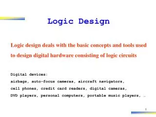
Standard Cell Design. Ch.5 Logic Design. TAIST ICTES Program VLSI Design Methodology Hiroaki Kunieda Tokyo Institute of Technology. Logic Design. RTL. RTL Simulation. Logic Synthesis. Synthesis Netlist. Functional Verification. Scan Path Design. Functional Verification. Scan

Ch.5 Logic Design
E N D
Presentation Transcript
Standard Cell Design Ch.5 Logic Design TAIST ICTES Program VLSI Design Methodology Hiroaki Kunieda Tokyo Institute of Technology
Logic Design RTL RTL Simulation Logic Synthesis Synthesis Netlist Functional Verification Scan Path Design Functional Verification Scan Netlist Timing Analysis
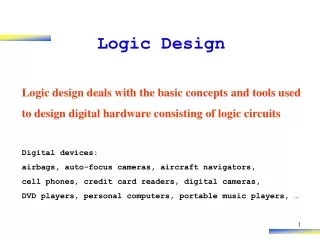
Logic Synthesis Problem • Map from logic equations to gate-level combinational logic • Goals • maximize speed • minimize power • minimize chip/board area • Constraints • target technology • CAD tool CPU time
Two-Level vs. Multi-Level E.g. Standard Cell Layout PLA control logic constrained layout highly automatic technology independent multi-valued logic input, output, state encoding Very predictable Multi-level Logic all logic general (e.g. standard cell, regular blocks,..) automatic partially technology independent some ideas part of multi-level logic Very hard to predict
General Logic Structure • Combinational optimization • keep latches/registers at current positions, keep their function • optimize combinational logic in between • Sequential optimization • change latch position/function
Optimization Criteria for Synthesis • The optimization criteria for multi-level logic is to minimizesome function of: • Area occupied by the logic gates and interconnect (approximated by literals = transistors in technology independent optimization) • Critical path delay of the longest path through the logic • Degree of testability of the circuit, measured in terms of the percentage of faults covered by a specified set of test vectors for an approximate fault model (e.g., single or multiple stuck-at faults) • Power consumed by the logic gates • Noise immunity • Placeability, Wireability • Manufacturability • while simultaneously satisfying upper or lower bound constraints placed on these physical quantities
5.2 Two Level Logic Synthesis
Example (Input Expansion) Perform logic simplification for the same output. If output is included by the other output, include the Simplification by adding as * or don’t care.
Example (Output Reduction) (4) Input parts is covered by (2). Output (1 1) is reduced to (0 1). F = A’B + C’D+AC G= A D + BC’D +AC
5.3 Multi Level Logic Synthesis
Algebraic Division and Boolean Division Algebraic Division F = g K+r where no common cube is included in g and K. F=(a+b)(c+d)+e The other division is Boolean Division. • F=(a+b)(a+c)+e
Problem of Multi level Logic Synthesis For several logic functions F[i], try to find common divisors such that F[i] = g[i] K+r[i] in a sense of algebraic division. ---->candidate K is restricted to Kernel, which can divide F[i] in algebraic manner. Objective function is the number of literals, which corresponds to size of circuit. F[i]=(ab+a’)(c+d’)+e (#literal =6)
Kernel 1. Literals: logic variable or its complement such as A, A’, B, B’ 2. Cube: logic product of literals such as A, AB, AB’ 3. Cubefree An expression is cube-free if no cube divides the expression evenly, that is ¬∃ C such that F=QC (no remainder), and C is a cube. 4. Kernel The kernel is a logic sum of product terms, which is a cube free. 5. Co-Kernel Co-kernel is a cube, which is a divisor of kernels.
Kernel 1. Literals: logic variable or its complement such as A, A’, B, B’ 2. Cube: logic product of literals such as A, AB, AB’ 3. Cubefree An expression is cube-free if no cube divides the expression evenly, that is ¬∃ C such that F=QC (no remainder), and C is a cube. 4. Kernel The kernel is a logic sum of product terms, which is a cube free. 5. Co-Kernel Co-kernel is a cube, which is a divisor of kernels.
Logic Design 2Kernel Example • F=abcd+abce+abef • Cofactors={1, ab, abc, abe} • Kernels={cd+ce+ef, d+e, c+f}
Method to find Kernel • Select literal and divide logic function • Repeat 1 until cube-free “sum of product” or cube is derived. • [Examples] F=abcd+abce+abef • 1. select literal a F1=F/a=bcd+bce+bef • 1.1 select literal b F2=F1/b=cd+ce+ef: cube-free (Kernel) • 1.1.1 select literal c F3=F2/c=d+e: cube-free (Kernel) • 1.1.2 select literal d F3=F2/d=c (cube) • 1.1.3 select literal e F3=F2/e=c+f: cube-free (Kernel) • 1.1.4 select literal f F3=F2/f=e (cube) • 1.2 select other literal x, but F1/x includes cube b • 2. Select other literal x, but F/x includes cube a • Cofactors={1, ab, abc, abe} • Kernels={cd+ce+ef, d+e, c+f}
Logic Function I d1=q1q0’+a’q1+bq0 d0=bq1’q0’+a’bq1’+a’bq0’ d1=q1q0’+a’q1+bq0
Logic Function II D0=bq1’q0’+a’bq1’+a‘bq0’ d0=bq1’q0’+a’bq1’+a’bq0’ D1=q1q0’+a’q1+bq0 d1=q1q0’+a’q1+bq0 • Derivation of Kernel • Kernel of d0={q1’q0’+a’q1’+a’q0’, q0’+a’, q1’+q0’ } • Co-kernel ={b, bq1’, a’b } • Kernel of d1={q1q0’+a’q1+bq0, q0’+a’} • Co-kernel ={1, q1} • 2) Step 2 Introducing a new variable c=q0’+a’ d0=b(cq1’+a’q0’) =b(cq1’+aq0’) d1=cq1+bq0
Scan Path Design RTL RTL Simulation Logic Synthesis Scan Netlist Functional Verification Scan Path Design Functional Verification Synthesis Netlist Timing Analysis
Logical Fault Model Stuck-at-0/1 Fault model : Logic value of wire segment is stuck at either logic 0 or logic 1. Single Fault: only one fault happens for each sample. Fault Test: logic circuit is tested by inserting various test input vectors and by observing its output, to check whether any single fault at each wire segment does not occur. ATPG: Automatic Test Pattern Generator is a CAD software to find out necessary input test vectors. Tester: in manufacture factory, tester is implemented so as to check volumes of chips in a short time, automatically.
Definition • Design for testability (DFT) refers to those design techniques that make test generation and test application cost-effective. • DFT methods for digital circuits: • Ad-hoc methods • Structured methods: • Scan • Partial Scan • Built-in self-test (BIST) • Boundary scan • DFT method for mixed-signal circuits: • Analog test bus
Scan Design • Circuit is designed using pre-specified design rules. • Test structure (hardware) is added to the verified design: • Add a test control (TC) primary input. • Replace flip-flops by scan flip-flops (SFF) and connect to form one or more shift registers in the test mode. • Make input/output of each scan shift register controllable/observable from PI/PO. • Use combinational ATPG to obtain tests for all testable faults in the combinational logic. • Add shift register tests and convert ATPG tests into scan sequences for use in manufacturing test.
Logic Design 4Scan Path Design In test mode, FFs are combined to shift register to set up data of FFs From outside of the chip through a test pin. In similar way, FF values are outputted to the outside of the chip. • Change to Test Mode • Down load test data to all FF, • Change to Run Mode • Run in one clock cycle • Change to Test Mode • Outputs result data from all FF • to output of LSI.
Level-Sensitive Scan-Design Flip-Flop (LSSD-SFF) Master latch Slave latch D Q MCK Q SCK D flip-flop SD Logic overhead TCK
Adding Scan Structure PI PO SFF SCANOUT Combinational logic SFF SFF TC or TCK SCANIN
Fault Table Fault Tableindicates the corresponding of test patterns against wire faults ①-⑯. The fault ⑤ include stuck-at-0 faults for wires l3 and l4. They are called equivalent fault, which cannot be distinguished by the test at outside. Five test patterns are selected, which can find inside fault by comparing calculated results and measured output against the selected test pattern.