Ch 8. Sequential logic design practices
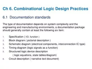
1. Documentation standards ▶ general requirements : signal name , logic symbol , schematic logic - state machine layout : a collection of F/F & combination logic on same - flip-flops : type , function , clocking behavior


Ch 8. Sequential logic design practices
E N D
Presentation Transcript
1. Documentation standards ▶ general requirements : signal name , logic symbol , schematic logic • - state machine layout : a collection of F/F & combination logic on same • - flip-flops : type , function , clocking behavior - state machine description : state table/diagram, transition list text files in H/W description language (VHDL) - Cascaded elements. - timing diagrams - timing spec : max.clockfreq , set-up & hold time min. pulse width Ch 8. Sequential logic design practices
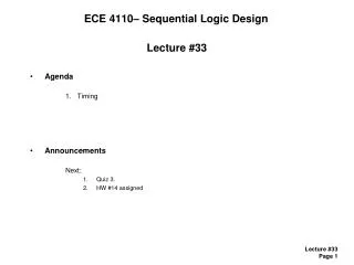
8.1.4 Timing Diagrams and Specification setup time margin = tclk – tffpd(max) – tcomb(max) – tsetup hold time margin = tffpd(min) + tcomb(min) + thold
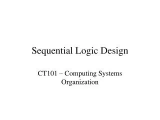
8.1.4 Timing Diagrams and Specification < Table 8 –1> Propagation delay in ns of selected CMOS flip-flops, registers , and latches
2. Latch & flip flops • 8.2.1 SSI Latches and flip flops
8.2.4 Bus Holder Circuit If pull-up resistor is too high, slow transition If pull-up resistor is too low, too much current Low & high -> floating Low <-> high Source or sink a small amount of additional current through R
8.2.5 Multiple Registers and Latches If EN_L = 1, Q <- Q If EN_L = 0, Q <- P
8.2.6 Registers and Latches in ABEL and PLDs Data1 in Rom is read Data2 in a different device is read
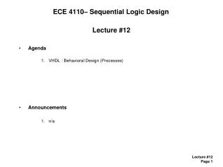
8.2.7 Registers and Latches in VHDL < Figure 7-12 D latch >
8.2.7 Registers and Latches in VHDL - Inferred latch - The code doesn’t say what to do if C ≠ 1, - The compiler infers a latch to retain the value of Q
8.2.7 Registers and Latches in VHDL < Fig 8-3 >
3. Sequential PLD • 8.3.1 Sequential GAL Devices
8.3.1 Sequential GAL Devices • No architecture control bits • More product terms 8-16 terms • Two more inputs
8.3.2 PLD Timing Specification ㆍA series PLD (ex : PAL26L8A ) : tPD = 25n , tCO =15n, tSU = 25 nsec ㆍSuffix : -5 , -7 , A, B,…
8.3.2 PLD Timing Specification ㆍtPD : propagation delay from input to output ㆍtCO : P-delay from rising edge of clock to output ㆍtSU (set-up), tcf( = tCO ), tH( hold) fmax : reliable max.freq ㆍ external PLD : PLD output -> connect to input of another PLD ㆍ internal PLD : same PLD
4. Counters state diagram = single cycles
8.4.1 Ripple Counters Ripple counter ㆍconnect in series or cascaded f/f ㆍCarry : ripples from LSB to MSB one bit at a time ㆍslow : n * tPTQ ( propagation delay of T f/f) CLK : applied to LSB F/F only
8.4.3 MSI Counters and Applications - MSI counter : Modulus N counter/divider i) Sync : ㆍ binary 4 bit counter ( 161,163 ) 161 : Async. clear function 163 : Sync. clear ( fully sync. counter ) ㆍ decade counter : 160, 162 ex) modulo-10 counter wavefarm < Fig 31> ㆍ 4 bit up/down counter : SN74169(TTL), 74C169(CMOS), CD40169(CMOS) up/down decade counter : 192 ii ) Async : ㆍ 4 bit binary counter : 193 ㆍ 12 counter : 92 ㆍ decade counter : 90 ㆍ 4 bit up/down counter : 191 ㆍ decade up/down counter : 190
8.4.3 MSI Counters and Applications RCO = 1 when OA = OB = OC = OD = 1 & ENT = 1