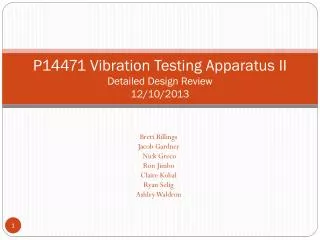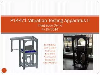
P14471 Vibration Testing Application
P14471 Vibration Testing Application. Team Introductions. Agenda. Background System Analysis Alternatives considered Selected system Test Plan Engineering Analysis Next Phase. Problem Statement. Update company’s vibration test apparatus Meet UL 844 Standard Vibration RPM Displacement

P14471 Vibration Testing Application
E N D
Presentation Transcript
Agenda • Background • System Analysis • Alternatives considered • Selected system • Test Plan • Engineering Analysis • Next Phase
Problem Statement • Update company’s vibration test apparatus • Meet UL 844 Standard • Vibration RPM • Displacement • Duration • Continue progress started by Team 13471 • Done: the eccentric drive mechanism • Still needs: • Frame • Motor • Control system
Project Deliverables • Completed frame • Appropriate motor selection and implementation • Motor speed control alternatives • Visual display • Frequency of oscillation • Displacement • Documentation • User Manual • Maintenance Manual • Test data verifying the operation of the apparatus
Alternatives Considered: Consider Systems Level Consider Systems Level
Alternatives Considered: Consider Systems Level Consider Systems Level
Morph Chart (Option 1) Screws Vertical Motor with Belt Laser Laser Software LED Screen Ear Plugs Belt Guard + Guard Plate Electroplating
Morph Chart (Option 2) Screws Vertical Motor with Speed Reducer Laser Laser Software LED Screen Ear Plugs Guard Plate Spray Paint
Morph Chart (Option 3) Screws Horizontal Motor with Flexible, Speed Reducing Coupling Laser Laser Software LED Screen Enclosure Enclosure Spray Paint
System Pugh Chart Why? Paint
Architecture Display/user interface Safety features Luminaire connection Sensors Central System Crankshaft connection Motor system Power supply
Test Plan • Test Displacement • Validate the 1/32” total displacement • Test Vibration Cycles • Validate 2000 cycles/min • Test fittings • Do they fit the frame? • Test User Interface • Check connections • Ease of use • Safety Evaluation
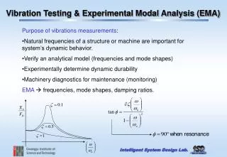
Engineering Analysis: Frame Analysis • Modeling frame in ANSYS Workbench • Using Modal Analysis to determine Natural Frequency • Next, stress and fatigue analyses will be performed on frame • Goal: 1. Prevent resonance in the frame 2. Prevent material failure 3. Prevent fatigue at connections
Engineering Analysis: Motor • A v-belt speed reducing system was selected because of its ability to provide the torque and speed necessary to run the machine at the standard and because of cost. • A direct coupling would have needed a 3500 RPM motor to run at less than 60% speed for 35 hrs at a time. This just isn’t possible with most motors. • Most speed reducing apparatuses are used to drastically increase torque output and don’t provide the speed ratio needed to run the crankshaft at 2000 RPM. They are also much more expensive than the belt system. Concept: Because of an increase in the radius, the driven pulley will be able to rotate at 2000 RPM while the driver pulley rotates at 3500 RPM when the proper ratio of radii is selected.
Engineering Analysis: Control System Open Loop System Closed Loop System
Engineering Analysis: Open Loop Control System • Two component system: • User input • Motor speed control • Multiple methods to control speed output: • Vary input voltage to the motor • Alter frequency of input signal to the motor • Change the number of stator poles
Engineering Analysis: Closed Loop Control System • Cycles per minute directly proportional to RPM • Three core components required for control: • Vibration speed sensor • Motor speed correction • Motor speed controller • Laser distance sensor to simultaneously measure vibration speed and displacement • Variable-Frequency Drive (VFD) to adjust speed • Microcontroller to accept sensor output measurement and feed corrected motor speed into VFD • Digital display for reading back measurements
Engineering Analysis: Closed Loop Feedback Laser Feedback System • Accuracy & precision on order of microns • Measurement frequency on order of kilohertz • Line of sight coincident with linear motion • Accurately sense each 1/32" displacement • Two consecutive changes in distance = 1 cycle • Analog output to feed into corrective circuit
Engineering Analysis: Control System Comparison • Open Loop System • Requires user input to adjust motor speed • Does not self correct with changing loads • Does not require a feedback system • Simple design to implement • Closed Loop System • Self correcting (no user input required) • Higher design budget • Integrates measuring devices with control system
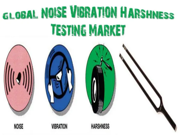
Engineering Analysis: Sound • L = dbA Sound Level • T = 8 hour exposure limit • C = actual exposure hours • Dosage Calculation: • D = 100 (C1/T1 + C2/T2 + C3/T3 +…) • D > 50% requires hearing protection • D > 80% requires engineering intervention https://www.osha.gov/pls/oshaweb/owadisp.show_document?p_table=STANDARDS&p_id=9736 http://www.industrialnoisecontrol.com/comparative-noise-examples.htm http://www.coopersafety.com/noisereduction.aspx
Engineering Analysis: Machine Guarding • General Industry (29 CFR 1910) • 1910.211(d)(44) "Pinch point" means any point other than the point of operation at which it is possible for a part of the body to be caught between the moving parts of a press or auxiliary equipment, or between moving and stationary parts of a press or auxiliary equipment or between the material and moving part or parts of the press or auxiliary equipment. • 1910.212(a)(1) Types of guarding. One or more methods of machine guarding shall be provided to protect the operator and other employees in the machine area from hazards such as those created by point of operation, ingoing nip points, rotating parts, flying chips and sparks. Examples of guarding methods are-barrier guards, two-hand tripping devices, electronic safety devices, etc. • Plus specifics for Electrical Markings, Lubrication Access, Belts, and more
Appendix /Reference Information • Laser Sensor • Long Range/High Accuracy Sensor • LK-G152/G157 Series • Range: 150 +/- 40mm • Accuracy: +/-0.05% • Sensor Speed: 50kHz • Repeatability: 0.5µm • Sources • http://www.keyence.com/products/measure/laser-1d/lk-g3000/applications/application-04.jsp • http://www.ia.omron.com/products/category/sensors/displacement-sensors_measurement-sensors/index.html
More Motor Information V-Belt Life: 25,000 hours (714 testing cycles) http://www.dodge-pt.com/products/pt_components/belts/belts.html