Download
1 / 80
810 likes | 999 Vues
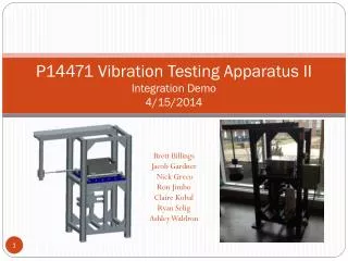
P14471 Vibration Testing Apparatus II Detailed Design Review 12/10/2013. Brett Billings Jacob Gardner Nick Greco Ron Jimbo Claire Kobal Ryan Selig Ashley Waldron. Agenda. Project Summary Selected Design Preliminary Analysis Frame Motor Electrical / Control System Safety

E N D
P14471 Vibration Testing Apparatus IIDetailed Design Review12/10/2013 Brett Billings Jacob Gardner Nick Greco Ron Jimbo Claire Kobal Ryan Selig Ashley Waldron
Agenda • Project Summary • Selected Design • Preliminary Analysis • Frame • Motor • Electrical / Control System • Safety • Improvements from P13471 • Test Plan • BOM • Project Plan • Concerns/Issues • Appendix
Problem Statement • Update company’s vibration test apparatus • Meet UL 844 Standard • Continue progress started by Team 13471 • Done: the eccentric drive mechanism • Still needs: • Frame • Motor • Control system
Selected Design • Interchangeable Conduits • Motor with V-belt • VFD • Digital Dial Gauge • Encoder • LCD, Microcontroller • Polycarbonate Guards • E-stop • Paint for Rust Protection
Maintaining Displacement • ER #1: Displacement must be 1/32’’ • Clamping force: • Provided by 2 x A574 screws - 5/8’’-11 • M = torque on screws • = 168.9 M ft-1 • Frictional force: • 2 possible locations: • = 33.8 M ft-1 (worst case) • Maximum force applied: • 1.68 ft-lbs. (motor) at 1/32’’ • = 645 lbs. • Required screw torque: • = 38 ft-lbs. (Safety factor of 2) • Max recommended A574 torque = 220 ft-lbs *Detailed calculations in Appendix 1 2
Engineering Analysis: Forces • ER # 12 – Maximum Luminaire Weight • Force on collar/conduit = 1641.3N (368.979lbf) • Force from connecting rod = 2822.68N (634.564lbf) • Calculated friction forces • Worst case = 297.68N (66.921 lbf) • Torque on connecting rod = 2.13667Nm (1.575 lbft) • Torque on block = 2.399Nm (1.769 lbft) • Torque on crankshaft = 2.399Nm(1.769 lbft) *Refer to Appendix
Engineering Analysis: Fatigue • Conduit • σa=15456.9psi so σm=0psi • σa<0.5*σ0 • Therefore Infinite Life • Factor of Safety • σar=15,5229psi < 0.5*σ0 • Infinite life • C-Channel • Max stress = 7181.27psi = σa • σa<0.5*σ0 • Infinite Life • Refer to appendix σ0 =35,000psi; σu =58,000psi
Engineering Analysis: Fatigue/Buckling σ0 =35,000psi; σu =58,000psi • Extension Rod: • Buckling: • Pcr = 4576.61lbf • 368.9 lbf < 4576.61lbf • No buckling • Fatigue: • σa=469.698psi • σa<0.5*σ0 • Infinite Life • Threaded Connector • Buckling: • Pcr = 13800.8lbf • 368.9 lbf < 13800.8lbf • No buckling • Fatigue: • σa=2855.26psi • σa<0.5*σ0 • Infinite Life • Refer to appendix
Frame Halve Views Front and Back Views of Crankshaft Front and Back Views of Full Assembly
Analysis Overview • ER # 2, 3 – Vibration of Luminaire, Test Duration • ER # 12 – Maximum Luminaire Weight • ER # 22 – Machine Footprint • ER # Tested both modal and harmonic response of frame using ANSYS Workbench • Simplified system to incorporate the respective weights of each system but not the complexity (bolt holes, threads, etc.) • Initially tested using a displacement of 0.015625” at the collar. This yielded: and • Tested using lower displacements and achieved a good result with a displacement of 0.0144” at the collar. This yielded: and
Motor Selection • ER #2 – Vibration of Luminaire • ER #10 – Max Motor Voltage • ER #12 – Maximum Luminaire Weight Maximum Load= 150 lbs Torque Necessary= 1.68 ft-lbs We will be running the motor at full load torque to allow for a longer life. With the v-drive offset, the motor can produce less torque than needed by the crankshaft system.
Motor Performance Data:Baldor M3545 We chose a 1 HP motor with a full-load torque of 1.5 LB-FT Updated cost from Volland Electric Equipment Corp: $237.51 *This is a saving of almost $235.00 from the original estimate
V-Drive Selection • ER #2 – Vibration of Luminaire • ER #4 – Isolate Motor from Oil Spills All information was gathered from the Dodge catalog For the given gear ratio of 1.75, Type A, 1-Groove Driver Datum Diameter: 3.4” Outer Diameter= 3.4”+.37”= Approx. 3.75” Driven Datum Diameter: 6.2” Outer Diameter= 6.2”+.37”= Approx. 6.55” Driver Taper Lock Bushing (1210), .5” Shaft Diameter Driven Taper Lock Bushing (1610), 1” Shaft Diameter Distance from center shaft to center shaft using donated belt guard: 9.5” *Unable to locate actual Dodge belt. A very similar belt will be purchased through AutoZone.
Encoder Placement The current shaft has to be machined down to a smaller size at the very end to add a coupling for the encoder. *Encoder to be discussed further in electrical systems
Power Supply • VGS-25-5 • 25 Watt 5V AC-DC converter • 5Amax delivered current • 3.1 x 1.11 x 2.03 inches *Refer to appendix for power calculations
Encoder TRD-N1024-RZWD • ER #2 – Vibration of Luminaire • ER #13 – Display System Status • Resolution: 1024 Pulses Per Revolution (PPR) • Max frequency: 100 kHz • Max RPM detection: 100 kHz / 1024 PPR * 60 = 5859 RPM
Enclosure • AMP1426CCLF • Polycarbonate enclosure with metal snap latch • 14 x 12 x 6 inches
Control System Pseudo Code • Initial delay to allow sufficient startup time for motor • Repeat (loop) the following until Timer_A value reads 35 hrs • Wait for appropriate delay time to avoid overworking MCU CPU • Use Timer_A capture from pin 11 of MCU to retrieve digital encoder signal • Read and store timer value upon rising edge of signal into var "A" • Read and store timer value upon next rising edge into var "B" • Period = B - A • Frequency = 1 / Period • Resolution = 1024 • Speed of vibration in RPM = Frequency / Resolution * 60 • ; Dimensions = (rev / min) = (pulses/sec) / (pulses/rev) * (60 sec/min) • Send RPM and elapsed time (also from Timer_A) to LCD display via pinouts • if RPM exists above safety threshold (2000 RPM + threshold) • exit loop with error code set high • Update VFD with new RPM information to step up or down accordingly • Send signal to alert VFD to bring motor to a complete stop • if error code set high • Write "Test Ended Abruptly: High RPM" to LCD display • else • Write "Test Completed Successfully" to LCD display
Launchpad and Display Encasing • ER # 3 – Duration of Vibration Test • ER #13 – Display System Status
Polycarbonate Guards • ER # 8 – Crankshaft Enclosure is Guarded • ER # 17 – Minimize Pinch Points • Top and rear guard • Clear, Polycarbonate ½’’ • Excellent impact resistance • Warning labels • Replace existing top guard • Move mounting holes away from edge • Increases strength, but slight overhang • Modify rear guard • Add access hole to decrease setup time
Belt Guard • ER # 17 – Minimize Pinch Points • Protects operator from 2000 RPM belt • Donated • Modifications required: • Convert to “split” type • Weld existing halves together • Cut guard in half in other direction • Change existing mounting brackets
Lock Out, E-stop • ER # 8 – Crankshaft Enclosure is Guarded • Lock out during maintenance • On electrical box, after power is isolated • Lock out procedure to be written in MSDII • ER # 9 – Completely Stop Machine with E-Stop • E-stop • Located on machine • Manually cuts power immediately
Engineering Analysis: Sound • ER # 16 – Low Sound • Hearing Protection / Engineering Intervention • To be determined in MSD II with Test Plan • Based on sound “dosage” • Dosage Calculation: • L = dBA Sound Level • T = 8 hour exposure limit • C = actual exposure hours • D = 100 * (C1/T1 + C2/T2 + C3/T3 +…) • D > 50% requires hearing protection • D > 80% requires engineering intervention https://www.osha.gov/pls/oshaweb/owadisp.show_document?p_table=STANDARDS&p_id=9736 http://www.industrialnoisecontrol.com/comparative-noise-examples.htm http://www.coopersafety.com/noisereduction.aspx
Safety Checklist • ER # 8 – Machine Guarding • ER # 9 – Emergency Stop • ER # 16 – Low Sound
Setup Improvements • ER # 11 – Minimize number of operators • ER # 14 – Steps to set up • ER # 15 – Setup time
Setup Improvements • Current setup procedure: • Measure displacement with dial gauge • Lockout machine • Remove top guard (8 screws) • Remove rear guard (4 screws) • Remove collars (2) • Remove connecting plate • Loosen locking bolts (2) • Adjust set screw • Perform 2-7 in reverse • Repeat 1-9 until 1/32’’ reached ~ 5x • Approximately 60 minutes to setup 2x 10 minutes
Setup Improvements • Displacement adjustment without removing rear guard, collars, or connecting plate • Also, U-bolt prevents block from rotating • Changes required: • Add 2 access holes to connecting plate • Add 4 holes total for u-bolt • Add 1 access hole to rear guard • Doesn’t impact safety, .2’’
Setup Improvements • Finer set screw • Before: • 11 threads per inch • 1 turn = 290% of displacement! • After: • 100 threads per inch • 1 turn = 33% of displacement • Changes required: • Machine new set screw plate • Requires threaded bushing for set screw
Set Up Improvements • Set screw • Account for excess space between conduit and collar • Flange • Dimensioned to be placed in same location every time • Blocks on the C channel • ER # 11 – Minimize number of operators • ER # 6, 19-21 – Mount 4 configuration types • ER # 13, 14 – Setup time, number of steps Flange Collar – crankshaft connection Collar – set screws
Test Plan • Displacement Test • Date Completed: ______________________ • Performed By: _______________________________