Download
1 / 22
220 likes | 415 Vues
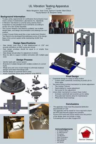
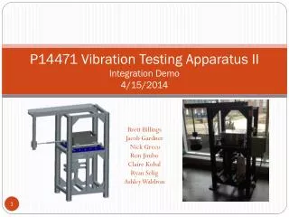
P14471 Vibration Testing Apparatus II Integration Demo 4/15/2014. Brett Billings Jacob Gardner Nick Greco Ron Jimbo Claire Kobal Ryan Selig Ashley Waldron. Agenda. Demo Items BoM & Budget Issues Project Plan Appendix. Demo Items. Mount 18 lb luminaire to 3/4'' conduit

E N D
P14471 Vibration Testing Apparatus IIIntegration Demo4/15/2014 Brett Billings Jacob Gardner Nick Greco Ron Jimbo Claire Kobal Ryan Selig Ashley Waldron
Agenda • Demo Items • BoM & Budget • Issues • Project Plan • Appendix
Demo Items • Mount 18 lb luminaire to 3/4'' conduit • Adjust displacement • Turn on VFD & motor, 500 RPM • Display RPM & elapsed time on LCD • End with E-Stop
BoM / Budget • Current costs: • Remaining costs: • VFD enclosure - $80 • Shipping to Syracuse - $600 • Travel Expenses - $240 • Expected final cost: $3,400 • https://edge.rit.edu/edge/P14471/public/WorkingDocuments/Detailed%20Design/BOM_rev6_tracking.pdf
Issues • Reinforce motor mount • Vibration noise at certain frequencies • Decide on Control Panel layout • Shipping apparatus to Syracuse Ryan
Selected Design • Interchangeable Conduits • Motor with V-belt • VFD • Digital Dial Gauge • Encoder • LCD, Microcontroller • Polycarbonate Guards • E-stop • Paint for Rust Protection
Safety Checklist • ER # 8 – Machine Guarding • ER # 9 – Emergency Stop • ER # 16 – Low Sound
Test Plans • Refer to Excel document • https://edge.rit.edu/edge/P14471/public/WorkingDocuments/MSDII_Build%20Test%20Documentation/P14471 Test Plans_Rev2.xlsx • or EDGE • https://edge.rit.edu/edge/P14471/public/Build%2C%20Test%2C%20Document
Maintaining Displacement • ER #1: Displacement must be 1/32’’ • Clamping force: • Provided by 2 x A574 screws - 5/8’’-11 • M = torque on screws • = 168.9 M ft-1 • Frictional force: • 2 possible locations: • = 33.8 M ft-1 (worst case) • Maximum force applied: • 1.68 ft-lbs. (motor) at 1/32’’ • = 645 lbs. • Required screw torque: • = 38 ft-lbs. (Safety factor of 2) • Max recommended A574 torque = 220 ft-lbs *Detailed calculations in Appendix 1 2
Setup Improvements • ER # 11 – Minimize number of operators • ER # 14 – Steps to set up • ER # 15 – Setup time
Setup Improvements • Finer set screw • Before: • 11 threads per inch • 1 turn = 290% of displacement! • After: • 100 threads per inch • 1 turn = 33% of displacement • Changes required: • Machine new set screw plate • Requires threaded bushing for set screw
Set Up Improvements • Set screw • Account for excess space between conduit and collar • Flange • Dimensioned to be placed in same location every time • Blocks on the C channel • ER # 11 – Minimize number of operators • ER # 6, 19-21 – Mount 4 configuration types • ER # 13, 14 – Setup time, number of steps Flange Collar – crankshaft connection Collar – set screws
Full Risk Analysis • See EDGE • https://edge.rit.edu/edge/P14471/public/ProjectManagement/Risk%20Analysis.pdf
VFD Damage Incident • See EDGE • https://edge.rit.edu/edge/P14471/public/WorkingDocuments/VFD%20Damage%20Incident/VFD%20Damage%20Incident.pdf