ENG3640 Microcomputer Interfacing
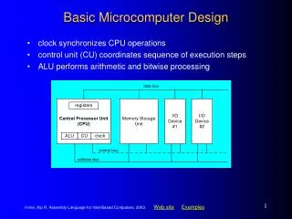
ENG3640 Microcomputer Interfacing. Week #3 Assembly Language Design and Structure. Topics. Stopping a Program. Software Delay Routine. Assembly Language Design and Structure. Program Structure and Organization. D-Bug12 Utility Routines. The CPU12 Instruction Set

ENG3640 Microcomputer Interfacing
E N D
Presentation Transcript
ENG3640 Microcomputer Interfacing Week #3 Assembly Language Design and Structure
Topics • Stopping a Program. • Software Delay Routine. • Assembly Language Design and Structure. • Program Structure and Organization. • D-Bug12 Utility Routines. • The CPU12 Instruction Set • Data Transfer • Logical Operations • Using the Stack • Subroutine Calls • Arithmetic Operations (Add, Sub, Mult, Div) ENG3640 Fall 2012
Resources • Huang, Chapter 4 Sections • 2.6 Program Loops • 2.10 Program Execution Time • 4.10 Using D-Bug12 Functions ENG3640 Fall 2012
STOP: stop processing stops internal clocks, puts the processor in the standby mode recovery from STOP may be accomplished by RESET^ or an interrupt Stop_here BRA Stop_here BRA (rel) Branch always Opcode: 20 Operation: PC ← (PC) + $002 + rr End Directive: any statement following the END directive will be ignored by the assembler. SWI: software interrupt When executed it stacks the registers, and executes an ISR. Works like a break point in your program. RECOMMENDED! Stopping a Program ENG3640 Fall 2012
Software Delay Routines • Software delay routines are used to synchronize the execution of a program with respect to time: • Temporarily display a message • To debounce a switch on a keyboard! • To wait for an EEPROM to be erased. • So in many applications the execution of a routine must be timed to meet external requirements. ENG3640 Fall 2012
Subroutine Program Flow bsr saves the PC on the stack before going to func. The rts instruction returns program flow to the instruction following the last subroutine call! Bsr func Bsr func func rts ENG3640 Fall 2012
Delay Routines: Issues • In order to design a software delay routine, we must know how to calculate the time it takes to execute the instructions that make up the routine! • Main problem with software delays is that their timing characteristics change if interrupts are used! • Also, the CPU has to have a deterministic instruction execution time (i.e. No pipelining!) ENG3640 Fall 2012
Instruction Timing • The instruction execution time is determined by: • Bus Frequency of the CPU • Number of cycles required by the instruction • The number of cycles depend on many things: • Size of opcode. • The number of arguments. • Size of the data bus. • Complexity of execution. ENG3640 Fall 2012
Program Execution Time The number of cycles executed by each Instruction are detailed in the CPU12 Manual ENG3640 Fall 2012
CPU12: Instruction Execution Time • To convert the number of cycles to time, we must know the bus frequency of the CPU • CPU12 bus frequency is based on the E-clock. • For the MC68HC12A4 the E-clock (FE) is one half of the oscillator or crystal frequency found on the XTAL and EXTAL inputs. • The crystal frequency of the MC68HC12A4 is 16MHz, so FE = 8MHz ENG3640 Fall 2012
CPU12: Total Execution Time • The total execution time (Tex) is then given by: Tex = N x TE where N = total number of clock cycles TE = the E-clock period, 1/FE ENG3640 Fall 2012
Simple Delay: Implementation ldx #1 ; [2] E cycles loop psha ; [2] E cycles pula ; [3] E cycles psha ; [2] E cycles pula ; [3] E cycles nop ; [1] E cycle nop ; [1] E cycle dbne x,loop ; [3] E cycles Total cycles 15 clock cycles (excluding ldx) @ 8MHz (125 ns) 125 x 15 = 1.875 uS ENG3640 Fall 2012
Example1: Simple Delay Example: Write an instruction sequence to create 100 ms time delay. Solution: • Previous loop takes 1.875 us • We have to find out the number that should be loaded with the index register x? • 100 ms / 1.875 us 53,333 ENG3640 Fall 2012
Example2: 100ms Delay Example: Write an instruction sequence to create 100 ms time delay. ldx #53333 ; [2] E cycles loop psha ; [2] E cycles pula ; [3] E cycles psha ; [2] E cycles pula ; [3] E cycles nop ; [1] E cycle nop ; [1] E cycle dbne x,loop ; [3] E cycles ENG3640 Fall 2012
Subroutine Dly1ms ;*********************************************************************************** ; Subroutine Dly1ms – 1ms delay loop. ; MCU : 68HC12, E=8MHz, no clock stretching, 16-bit bus ; Registers : Preserve index register x. ; Stack Reqs: 2 bytes stack space Dly1ms pshx ; [2] ldx #TC1MS ; [2] d1mslp dex ; [1] bne d1mslp ; [3/1] pulx ; [3] rts ; [5] We need to find the value of TC1MS!! ENG3640 Fall 2012
Dly1ms N = 14 + (4 * TC1MS) ; 14 cycles outside the loop ; 4 cycles inside the loop For a delay of 1ms we need N = TEX/TE = 1ms/125ns = 8,000 cycles ; Recall TE = 1/FE This requires a loop count TC1MS of: TC1MS = (N-14)/4 1,996.25 1,996 ENG3640 Fall 2012
Program Contents and Organization The objective is to illustrate the program organization and give an example of a programmable delay and show you how I/O ports can be used within the CPU12. • Program Header • Equates (port definitions e.t.c.) • Constants • Variables • Main Program • Subroutines ENG3640 Fall 2012
Program Contents: Header • Program Header (functional description of program, list program dependencies, revision date, name) ;**************************************************** ;* A simple demonstration program ;* It generates 60 1-second, active low, pulses on PH0 ;* MCU : 68HC12A4, E= 8MHz ;* Monitor: D-Bug12 ;* ;* Date: 20/09/2012 ;* Author: ShawkiAreibi ;***************************************************** ENG3640 Fall 2012
Program Contents: Equates • Equates: should follow the program header. By using equates you can use symbol names to make the code more readable. ;****************************************************************** DDRH EQU $25 ; Port Definition PORTH EQU $24 BIT0 EQU %00000001 TC1MS EQU 1996 ; Delay Count for 1ms ;****************************************************************** ENG3640 Fall 2012
Program Contents: Constansts & Variables • Stored constants: The stored constants are defined after all the program code. • Variables: Variables are places at the end of the program. One thing unique about variables is that they must be placed in RAM. During development the whole program is placed in RAM, so there is not another origin statement for the variables. ;********************************************************************************* ; Constants ;********************************************************************************* InitCnt fcb 60 ; initial pulse count ;********************************************************************************* ; Variables ;********************************************************************************* CurCnt rmb 1 ; LED flash counter ENG3640 Fall 2012
Program Contents: Main Program • Main Program: After equates there should be an origin directive to define the starting location of the program code. The main program follows the ORG directive. ;****************************************************************** ORG $0800 Main bset DDRH, BIT0 ; Initialize PORTH, BIT0 bset PORTH, BIT0 movb InitCnt, CurCnt ; Initialize pulse counter ; InitCnt defined in Constant Section ; CurCnt defined in Variable Section ;****************************************************************** ;* Main loop for output pulse generation ;****************************************************************** ENG3640 Fall 2012
Cont … Main Program ORG $0800 Main ; Initialization Section ;****************************************************************** ;* Main loop for output pulse generation ;****************************************************************** Pulse bclr PORTH, BIT0 ; Turn pulse off ldd #250 ; Wait for 250ms jsr WaitDms ; WaitDms is a programmable delay bset PORTH, BIT0 ; Turn pulse on ldd #750 jsr WaitDms dec CurCnt ; Count pulses? bne pulse ; No: Another pulse swi ; Yes: Return to monitor ENG3640 Fall 2012
Program Contents: Subroutines • All subroutines and interrupt service routines, should follow the main program. Subroutines themselves should never be contained within the main program code or another subroutine. ;*********************************************************************************** ; Subroutine WaitDms – A programmable delay in ms. ; Arguments : The number of ms is passed in ACCD ; Registers : Preserve all registers except CCR. ; Stack Reqs: 6 bytes stack space ; Req. subs : Dly1ms ;************************************************************************************ WaitDms pshd ; preserve ACCD msdlp jsr Dly1ms ; execute 1ms ACCD times subd #1 bne msdlp puld rts ENG3640 Fall 2012
Program Contents: Subroutines ;*********************************************************************************** ; Subroutine Dly1ms – 1ms delay loop. ; MCU : 68HC12, E=8MHz, no clock stretching, 16-bit bus ; Arguments : None ; Registers : Preserve all registers except CCR. ; Stack Reqs: 2 bytes stack space ; Req. subs : None ;************************************************************************************ Dly1ms pshx ; preserve IX ldx #TC1MS ; execute loop TC1MS times d1mslp dex bne d1mslp pulx rts ENG3640 Fall 2012
Program Organization ;********************************************** ; Program Header ;********************************************** ; Equates ;********************************************** ; Constants ;********************************************** ; Variables ;********************************************** ; Main Program ;********************************************** ; Subroutines ;********************************************** ENG3640 Fall 2012
D-Bug12 Utility Routines • A stable operating environment is required to develop microcontroller software. • One of the simplest most economical development environments consist of a monitor/debugger program that resides in ROM and executes in the target environment. • A ROM monitor provides • Environment for controlled execution of software • Utility routines to aid in testing new algorithms. ENG3640 Fall 2012
D-Bug12 Utility Routines • The utility routines are presented as C function definitions in the Motorola Application Note ``Using and Extending D-Bug12 Routines” because the D-Bug12 was written almost entirely in C. • The utility routines are usable when: • Programming inC • Programming in Assembly Language! ENG3640 Fall 2012
D-Bug12 Utility Routines (check Appendix C of Lab Manual of Web) ENG3640 Fall 2012
Assembly Source for isdigit( c ) ;*********************************************************** ; isdigit(c) ; Description: A routine to check if an ASCII char is a digit (0..9) ; Arguments: Char is passed in ACCB ; Return value is passed in ACCB and Z bit of CCR ;*********************************************************** Isdigit cmpb #’0’ blo isd_not Isd_9 cmpb #’9’ bhi isd_not ldab #1 bra isd_rtn Isd_not clrb Isd_rtn rts ENG3640 Fall 2012
Assembly Language Interface Calling a function from assembly language is simple. • First push the parameters onto the stack in the proper order. • Call the function with a JSR instruction. • The JSR instruction uses a form of indexed indirect addressing that treats the Program Counter as an index register. • Results are returned in the D Accumulator. • Char values returned in the D Accumulator are located in B • Boolean function results are zero for False and non-zero for True. • Called functions preserve only the content of the stack pointer. If other CPU12 register values must be preserved, they must be pushed onto the stack before any of the parameters and restoredafter deallocating the parameters. ENG3640 Fall 2012
int getchar(void) • The getchar() function retrieves a single character from the control terminal SCI • If a character is not available in the SCI Receive Data Register when the function is called, getchar() waits until one is received. • Because the character is returned as an int, the 8-bit character is placed in the B Acc. ENG3640 Fall 2012
Int printf(char *format) • The printf() function is used to convert, format, and print its arguments as standard output (the output device could be the monitor screen, printer, LCD, etc) under the control of the format string pointed to by format. • Formatted characters supported by the printf() function are • d,i signed decimal number • c single character • s string until a `\0’ (NULL) ENG3640 Fall 2012
Example: Utilizing getchar(), printf() CR EQU $0D ; ASCII for Carriage Return LF EQU $0A ; ASCII for Line Feed getchar EQU $EE84 ; Address of getchar() printf EQU $EE88 ; Address of printf() ORG $1000 ; Start address of vars/constants msg db “char pressed is %c”,CR,LF,0 ORG $1100 ; Start address of main program getnewval LDX getchar ; load address of getchar subroutine JSR 0,X ; get char from keyboard CMPB #$1B ; check if the char is an ESC char BEQ terminate ; jump to end of program PSHD ; push char on stack for printf subroutine LDD #msg ; second parameter in ACCD LDX printf ; load address of printf subroutine JSR 0,X ; print message on terminal BRA getnewval ; repeat getting new chars terminate SWI ; end of program ENG3640 Fall 2012
Instructions: Classificaions • Data handling (Data Transfer) • Arithmetic (Addition, Subtraction, ..) • Subroutines • Logic Operations (AND, OR, ..) • Bit Test and Manipulation • Branches and Jumps • Conditional Branches ENG3640 Fall 2012
Data Handling: Register Loads To transfer an immediate value or a value from memory to a register, a load instruction is used. ENG3640 Fall 2012
The last three instructions in previous table are “load effective address instructions”. Load Effective Address Example leas 4, SP ; SP+4 SP leay d, y ; IY+ACCD IY Load Effective Address ENG3640 Fall 2012
Data Handling: Register Store To transfer data from a register to memory, a store instruction is used. ENG3640 Fall 2012
Transfers and Exchanges To move data between two registers, transfer and exchange instructions are used.
The CPU12 added a general-purpose transfer and a general-purpose exchange to replace the CPU11 register specific transfers and exchanges. tfr a, b ; ACCA ACCB tab ; ACCA ACCB (Compatible CPU11) Note: the tab instruction affects the CCR, whereas the tfr has no effect on the CCR! If a transfer occurs from a 16-bit register to an 8-bit register, the Least Significant Byte of the source register is copied to the destination register. If a transfer occurs from an 8-bit register to a 16-bit register, CPU12 automatically performs a sign extension into the most significant byte of the destination register. Transfers and Exchanges ENG3640 Fall 2012
Move Instructions • The memory-to-memory move instruction is another new instruction that significantly improves code efficiency in the CPU12. • It enables you to either move data from one memory location to another or move immediate data into a memory location without using CPU register. ENG3640 Fall 2012
Move Instructions Examples ************************************************************** movb #$0F, PORTJ ; $0f PORTJ ldaa #$0F ; CPU11 Equivalent staa PORTJ *************************************************************** movw 0,x,0,y ; (IX:IX+1) (IY:IY+1) ldd 0,x ; CPU11 Equivalent std 0,y ENG3640 Fall 2012
Shift and Rotate Instructions The 68HC12 has shift and rotate instructions that apply to a memory location, accumulators A, B and D. A memory operand must be specified using the extended or index addressing modes. Logical Shift Shift Left (Memory,A,B,D): LSL,LSLA,LSLB,LSLD Shift Right (Memory,A,B,D): LSR,LSRA,LSRB,LSRD Arithmetic Shift, Similar to a Logical shift, but the sign bit remains unchanged. Shift Left (Memory,A,B,D): ASL,ASLA,ASLB,ASLD Shift Right (Memory,A,B,D): ASR,ASRA,ASRB Cyclic Shift (or Rotation) Left (Memory,A,B): ROL, ROLA,ROLB Right (Memory,A,B): ROR, RORA,RORB ENG3640 Fall 2012
Shift and Rotate Instructions A common application for the shift and rotate? multiplication and division. Shifts can be used to multiply or divide by constant powers of 2. ENG3640 Fall 2012
Boolean Logic, Bit Manipulation Boolean logic functions are important for bit manipulation such as setting, clearing or inverting individual bits in a word. ENG3640 Fall 2012
Clearing Bits: use the AND Instruction X.1 = X X.0 = 0 A7A6A5A4 A3A2A1A0 . 0 0 0 0 1 1 1 1 -------------------------- 0 0 0 0 A3A2A1A0 Bit Manipulation “Clearing Bits” ENG3640 Fall 2012
Setting Bits: use the OR Instruction X + 1 = 1 X + 0 = X A7A6A5A4 A3A2A1A0 + 0 0 0 0 1 1 1 1 -------------------------- A7A6A5A4 1 1 1 1 Bit Manipulation “Setting Bits” ENG3640 Fall 2012
Inverting Bits: use the XOR Instruction X (XOR) 1 = X’ X (XOR) 0 = X A7A6A5A4 A3A2A1A0 XOR 0 0 0 0 0 0 0 1 -------------------------- A7A6A5A4 A3A2A1A0’ Bit Manipulation “Inverting Bits” ENG3640 Fall 2012
CCR Flag Manipulation There are individual instructions for setting and clearing CCR flags ENG3640 Fall 2012
The Stack • Conceptually, a stack is a list of data items whose elements can be accessed from only one end. • A stack element has a top and a bottom. • The operation that adds a new item to the top is called push. • The top element can be removed by performing an operation called pop or pull. Stack • The Stack Pointer (SP) points to the top element or to the memory location above the top element.
Using the STACK The stack is LIFO data structure. It is an ideal data structure for temporarily storing data from nested routines ENG3640 Fall 2012