Download
1 / 17
241 likes | 426 Vues
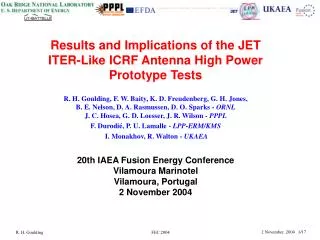
Results and Implications of the JET ITER-Like ICRF Antenna High Power Prototype Tests. R. H. Goulding, F. W. Baity, K. D. Freudenberg, G. H. Jones, B. E. Nelson, D. A. Rasmussen, D. O. Sparks - ORNL J. C. Hosea, G. D. Loesser, J. R. Wilson - PPPL F. Durodié, P. U. Lamalle - LPP-ERM/KMS

E N D
Results and Implications of the JET ITER-Like ICRF Antenna High Power Prototype Tests R. H. Goulding, F. W. Baity, K. D. Freudenberg, G. H. Jones, B. E. Nelson, D. A. Rasmussen, D. O. Sparks - ORNL J. C. Hosea, G. D. Loesser, J. R. Wilson - PPPL F. Durodié, P. U. Lamalle - LPP-ERM/KMS I. Monakhov, R. Walton - UKAEA 20th IAEA Fusion Energy Conference Vilamoura Marinotel Vilamoura, Portugal 2 November 2004 FEC 2004
Outline • Motivation • Description of the JET ITER-Like Antenna High Power Prototype (HPP) • Test results • Conclusions FEC 2004
The challenge • The H-mode operating scenario presents difficulties for ICRF (Ion Cyclotron Range of Frequencies) heating systems attempting to operate at their design power level • The steep edge density profile reduces plasma loading • ELMs produce order of magnitude increases in plasma loading, leading to an impedance mismatch at the generator • ELMs also can lower the threshold voltage for breakdown in the ICRF launcher • ITER additionally • Will have a large gap between the antenna and plasma separatrix ( ~150mm) • Advanced operating modes such as Weak Negative Shear will have reduced edge plasma density FEC 2004
Trend In ICRF Launcher Design: Decrease sensitivity to target plasma characteristics • Design goal: • 20 MW through single port, 40-55 MHz • produce launcher with input impedance insensitive to changes in loading • minimize electric fields in antenna structure for a given level of current on radiating elements • Note: recent advances in 3-D electromagnetic modeling capabilities are proving very useful! (Discussed later…) ITER ICRF Launcher (Baseline Design) FEC 2004
The JET ITER-Like Antenna and High Power Prototype Faraday screen removed • Test design principles on JET • ITER-Like Antenna designed to couple 7.1 MW (8 MW/m2) into an ELMy H-mode plasma • Maintains match during ELMs and other transients causing increases in resistive loading (VSWR < 1.5, allows rf generator to couple full power into antenna) • High power prototype is quadrant of full antenna JET ITER-Like ICRF Antenna FEC 2004
Key: voltage probe fluoroptic temperature sensor High Power Prototype (HPP) FEC 2004
The HPP has several novel design features such as the integral quarter-wave impedance transformer Impedance transformer inner conductor with capacitors and plug-in flanges Motors Inner conductor installation Impedance transformer outer conductor Removable panels FEC 2004
Another feature is the internal matching capacitors with “plug-in” flanges and non-contact temperature monitoring 80 Temperature °C 30 0 6 Time (hrs) FEC 2004
Major objectives have been met • Plug-in capacitor flanges have not experienced any problems over several installation cycles • Good agreement observed between measured characteristics of matching circuit and model results • Observed voltage limits exceeded target value for short pulses • Long pulse operation coupled sufficient power for 10 s to reveal two design weaknesses, both related to rf dissipation in the antenna structure • High current density in flexipivot (more details later…) • Excessive heating at edges of current straps • Temperature increases at uncooled capacitor ends similar to predicted values • Most novel features performed very well FEC 2004
Short pulse tests exceeded 42 kV target value • Voltage initially limited to 24 kV at capacitors. Problem identified as arcing between tiles and Faraday screen rods • After left-side private limiter tiles removed, voltage limit nearly doubled ( 24 kV 45 kV) • Tiles have been redesigned to increase gap to 10 mm Arc damage observed Pin = 350 kW f = 50 MHz FEC 2004
Long pulse test results Chamber pressure • Maximum voltage ~ 20 kV • Voltage and power limited by outgassing likely caused by strong localized heating • Breakdown occurs for chamber pressures above 10-4 Torr (.013 Pa) • Measured increases in capacitor temperatures were acceptable Capacitor temperatures 4.5 hrs FEC 2004
Thermal glows were observed during long pulse operation Top strap Bottom strap FEC 2004
Thermal glows were observed during long pulse operation Top strap – followed by arc Bottom strap FEC 2004
Problem traced to excessive local heating at flexipivot Infrared Visible light top • Flexipivot: another new feature - 2 parallel Inconel 718 plates, 2mm thick, with 2mm gap in between • Reduces thermal stresses on Be Faraday screen bars • Low disruption stresses (thin, high resistivity) • Temperature exceeded 1290 °C • High temperature region very localized flexipivot damage FEC 2004
Subsequent modeling with CST Microwave Studio (MWS) reveals current concentration precisely where damage occurred • Results were fed into ANSYS thermal model • Highest calculated temperatures seen in same localized region as damage front bottom Current density (represented by color and size of current vectors) FEC 2004
Problem solved by incorporation of wedges to redistribute rf currents • ANSYS model shows flexipivot now remains cool. • Small "hot spot" at base of thicker wedge is lower in temperature; will be further lowered by fabricating from Ni • Wedges (installed top and bottom) do not interfere with mechanics of flexipivot FEC 2004
Conclusions, future work • The HPP has proven its worth. The approach – extensive modeling together with construction and testing of a high fidelity prototype has • led to several important design improvements for the JET ITER-Like antenna • as well as improved design, construction, and testing techniques • Voltages > 45 kV have been achieved, confirming basic voltage handling capability. • 10 s pulses have been achieved at maximum voltage of 25 kV, with sufficient dissipated power to reveal areas of design requiring improvement • Improved 3-D EM modeling has qualitatively replicated problem believed responsible for long pulse power and voltage limits. Full HPP model under construction • HPP being refurbished, will be used to test redesigned current straps (new –fabrication process: investment castings), wedges, and new capacitor design in Spring 2005 • ORNL and PPPL will participate extensively in commissioning and operation of the actual JET ITER-Like antenna FEC 2004