Vacuum Tube Lifters Basic Overview
Vacuum Tube Lifters Basic Overview. Vacuum Lifting. How to quote a Vacuum Tube Lifter . You may also add ancillary items such as Universal Joint or Lower Rotary Coupling. Typical System Layout . Typical System Layout . Typical System Layout . Typical System Layout . Tube Assembly .


Vacuum Tube Lifters Basic Overview
E N D
Presentation Transcript
Vacuum Tube Lifters Basic Overview
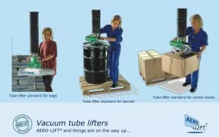
How to quote a Vacuum Tube Lifter You may also add ancillary items such as Universal Joint or Lower Rotary Coupling
Tube Assembly Vacuum 360o Rotary Safety Plate Support Rope Vacuum
Lift Tube Range - MiniLifter (ML) Note: Capacities shown do not include end effector or ancillary items e.g. Universal Joint
Lift Tube Range - Pal-U-Lift (PL) Note: Capacities shown do not include end effector or ancillary items e.g. Universal Joint
Lift Tube Range - High Capacity (HCL) Note: Capacities shown do not include end effector or ancillary items e.g. Universal Joint
MiniLifter (ML) Control Valves – partial listing ML-TV Trigger type ML-HV Horizontal type ML-FEHV Flexible extension to horizontal handle
Pal-U-Lift (PL) Control Valves – partial listing PL-SPL Stay-Put PL-SLL Spring Loaded PL-SPT Throttle type PLE-SPL Extended PL-SLL Flexible Extended
High Capacity (HCL) Control Valves – partial listing HCLE-SPL Extended with Stay-Put HCLFE-SLL Flexible Extended with Stay-Put
Safety Ratios – cups are sized to match tube diameter safety ratio of 2.5:1 for horizontal and 4.0:1 for vertical
Ancillary Items – partial listing Lower Rotary Universal Joint Angle Adaptor Angle Adaptor c/w Gas Strut
Ancillary Items – partial listing Lift-Off fitted to PL-SPL Control Handle Lift-Off fitted to a ML Control Handle
Trolley Pin Height Checking Compacted Height of SLTA or MLTA assembly + Ancillary + Controls + End Effector + 67 inches (stroke) to give o/a height for trolley pin elevation (add 2 inches to total to give clearance above floor)