Vacuum Tube Amplifier
Vacuum Tube Amplifier. Team Members: Matt Andrews and Yuriy Kharin Project Adviser: DR. Michael Carter. ECE791 Fall 2010. Objective. The objective of this project is to become familiar with vacuum tubes and vacuum tube amplifiers

Vacuum Tube Amplifier
E N D
Presentation Transcript
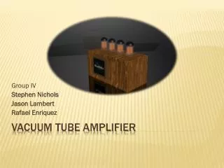
Vacuum Tube Amplifier Team Members: Matt Andrews and YuriyKharin Project Adviser: DR. Michael Carter ECE791 Fall 2010
Objective The objective of this project is to become familiar with vacuum tubes and vacuum tube amplifiers As seniors in electrical engineering and having had an experience with solid state transistors in the classroom and laboratory, we want to explore an alternative way of electrical signal amplification
Why the vacuum tubes are still in use Very Linear even when driven in saturation region Can be used in high voltage circuits Able to withstand over-voltage and a lot of heat for minutes where transistors would blow out in milliseconds Subjectively has “warmer” sound based on numerous Audiophiles
Goal Design and build audio vacuum tube amplifier Design and build the power supply 25 Watts 4 stages Be able to drive an 8 ohm speaker
Design Approach Specify Output Power with a given input signal Choose Operation configuration and mode Determine whether phase splitter is needed Determine required voltage gain Design Power Supply
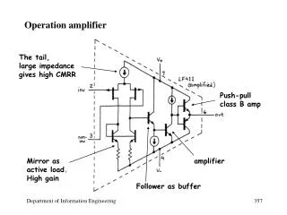
Input Stage High Input Impedance One half of a 6SN7 dual triode Common Cathode Configuration Provides some voltage gain
Phase Splitter Needed for Push-Pull Configuration Splits single signal into two signals Equal Magnitude, Opposite phase Concertina Type Equal Resistors at cathode and anode One half of 6SN7 tube
Driver Stage Used to drive output stage Provides voltage gain One 6SN7 dual triode tube
Output Stage Push Pull Configuration Class AB1 Operation Two 6L6 Beam Power Tetrodes Output transformer Negative Feedback
Power Supply • Select a power transformer based on the tubes’ voltage and current ratings • Step up to 360V peak • Current rating of at least 128mA • Full-wave diode rectifier with ratings of at least 5A • Smoothing Capacitor and RC smoothing network for ripple voltage elimination • Voltage divider network to supply the needed voltage to differently rated tubes/components
Testing Total Gain Power output Frequency Response