Introduction to Powder X-ray Diffraction
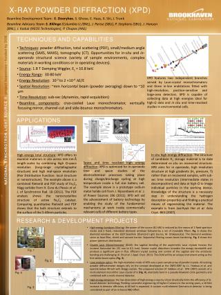
500 likes | 2.39k Vues
Introduction to Powder X-ray Diffraction. 18 th National School on Neutron and X-ray Scattering Cora Lind-Kovacs Department of Chemistry & Biochemistry The University of Toledo, Toledo, OH. History of Powder Diffraction. Discovery of X-rays: Roentgen, 1895 (Nobel Prize 1901)

Introduction to Powder X-ray Diffraction
E N D
Presentation Transcript
Introduction to Powder X-ray Diffraction 18th National School on Neutron and X-ray Scattering Cora Lind-Kovacs Department of Chemistry & Biochemistry The University of Toledo, Toledo, OH
History of Powder Diffraction • Discovery of X-rays: Roentgen, 1895 (Nobel Prize 1901) • Diffraction of X-rays: von Laue, 1912 (Nobel Prize 1914) • Diffraction laws: Bragg & Bragg, 1912-1913 (Nobel Prize 1915) • Powder diffraction: Developed independently in two countries: • Debye and Scherrer in Germany, 1916 • Hull in the United States, 1917 • Original methods: Film based • First commercial diffractometer: Philips, 1947 (PW1050) • Detectors and optics have improved a lot, but basic design remains similar! http://www.msm.cam.ac.uk/xray/images/pdiff3.jpg
Original Powder Setups • Oldest method: Debye-Scherrer camera • Capillary sample surrounded by cylindrical film • Simple, cheap setup Cullity; “Elements of X-ray Diffraction”
Physical Basis of Powder Diffraction • Powder diffraction obeys the same laws of physics as single crystal diffraction • Location of diffraction peaks is given by Bragg’s law • 2d sin = n • Intensity of diffraction peaks is proportional to square of structure factor amplitude • . ·exp[-82u2(sin2()/2]
Scattering of X-rays and Neutrons by Atoms • The structure factor equation contains a factor that describes the scattering power of atoms • Atomic scattering factor (form factor) fj for X-rays • Depends on number of electrons in atom and Q ( sin/) • Undergoes large changes close to absorption edges • Scattering length bj for neutrons • Depends on isotope, independent of Q • For some isotopes, bj can be negative
Resonant X-ray Scattering Experiments • Also referred to as “anomalous diffraction”; this type of experiment is carried out close to an absorption edge • The elastic scattering is given by f(E,Q) = fo(Q) + fo’(E,Q) + I fo’’(E,Q) • f and f undergo drastic changes close to the absorption edges of atoms • Great way to emphasize contribution of specific atoms • Especially useful for mixed site occupancies • In most cases, multiple patterns at different wavelengths are collected and analyzed simultaneously
Absorption Edges and Anomalous Scattering • f “mirrors” the absorption coefficient • f is intimately related to the absorption coefficient
Neutrons: Coherent and Incoherent Scattering • For X-ray diffraction, we are generally only concerned with coherent elastic scattering • For neutron powder diffraction, we would like to only deal with coherent elastic scattering, but need to be aware of incoherent scattering as well • Phase is lost during incoherent scattering • Contributes to background • Less of an issue for single crystal experiments, but can be very significant for powder experiments • H is one of the worst culprits (not D!) – a few atom% cause problems
Goal of crystallography: Get structure • Single crystal experiments • Grow crystals (often hardest step) • Collect data (usually easy, both access and setup) • Determine unit cell (very easy for good quality single crystal) • Reduce data and solve (=determine approximate structure) (often easy) • Optimize structure (=refinement) (requires some care) • Powder experiments • Prepare powder sample (often easy) • Collect data (usually easy, but easy to make mistakes, too!) • Determine unit cell (can be very hard) • “Solve structure” (can be even harder – requires expert knowledge!) • Optimize structure – Rietveld refinement (requires considerable care)
What is a Powder? • A perfect powder sample consists of an infinite number of small, randomly oriented crystallites • Note that this is the underlying definition for many quantitative analysis methods! • In real life, the number is of course not infinite, but should be large to give good averaging • Small particle size: 1-5 m is ideal • “Powder samples” can come in many different forms: • Loose powders • Films, sheets, blocks, wires… • Basically any “polycrystalline” sample can be used in PXRD – if it is not a single crystal, it is considered a “powder sample”
Observations from Single Crystals • For a single crystal, there is one orientation in real space, resulting in one orientation of the reciprocal lattice • reciprocal lattice points are resolved and will result in diffraction intensity when they touch the Ewald sphere • Rotating the crystal rotates the reciprocal lattice Real space Reciprocal space Real space Reciprocal space
Observations from Powders • A powder sample consists of many crystallites with random orientations • we get many overlapping reciprocal lattices, resulting in a “sphere” of reciprocal lattice points that fulfill the Bragg condition at a given 2 • the sphere will intersect the Ewald sphere in a circle • we will observe “powder rings” Cullity; “Elements of X-ray Diffraction”
Somewhere in Between Anything from “several single crystals” to “almost homogeneous” is possible! Often referred to as “graininess problem” (e.g., not enough grains in the beam). Can result in non-random integrated intensities.
6000 5000 4000 3000 2000 1000 0 1 1.5 2 2.5 3 3.5 4 4.5 5 Q Powder Data Display Q = 4 sin /
Why Use Powder Diffraction? • Originally, powder diffraction was mainly used for phase identification • Advantages over single crystal methods: Can be used on ANY sample • If you can mount it, you can measure it! • For some materials, single crystal growth is difficult or impossible • Powder methods are the only option • “Real life samples” rarely come as single crystals: Engineering materials, formulations etc. • Powder diffraction can be used on mixtures of compounds • Peak shape analysis gives insights into size, stress and defects
Powder crystallography before Rietveld • Primary strategy: AVOID when it comes to structure determination! • There was no straightforward way to deal with data • Had to manually integrate intensities • Overlapping reflections were a big problem • Usually discarded • Alternative: Rewriting of single crystal software to refine using sums of overlapped reflections • Powder pattern simulation was more common • Relatively straightforward • Conclusions drawn based on similarities between patterns (e.g., isostructural compounds) • Visual comparison • Main use of powder diffraction was for phase identification
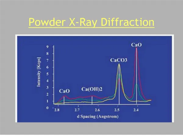
Modern Use: What Information Can We Get From Powder Diffraction Data? • Phase identification (qualitative phase analysis) • Most important/frequent use of PXRD • Qualitative analysis tool • Search pattern against database to identify phases present • Starting materials, known target compounds, likely impurities • Assumption: The material, or an isostructural material, is in the database • Phase fraction analysis (quantitative phase analysis) • Applied to mixtures of two or more crystalline phases • Compare intensities of selected peaks of all phases • Theoretically only requires one peak/phase, but better with multiple peaks • Accurate analysis requires standardization • Mix known quantities of two phases in several different ratios • Caution: Possibility of amorphous components
What Information Can We Get From Powder Diffraction Data? (Cont’d) • Lattice parameters • Two modes of analysis: • Accurate lattice parameters for a compound of known structure • Unit cell determination for an unknown compound through indexing • ACCURATE peak positions are crucial! • Rietveld refinement (structural analysis) • Least squares based minimization algorithm to obtain the best fit between a structural model and a powder pattern • Starting model necessary to apply this method • Applicable to simple and complicated structures, single phase and multi-phase samples • Automatically gives phase fractions and lattice parameters from ALL peaks • Requires good data for meaningful results
What Information Can We Get From Powder Diffraction Data? (Cont’d) • Structure Determination from Powder Data (SDPD) • Powder diffraction is subject to the same laws of physics as single crystal diffraction, but data overlap • Careful analysis can allow determination of unknown structures • Usually done with high quality synchrotron and/or neutron data • Requires excellent data and sound crystallographic knowledge! • Phase transition behavior • In situ diffraction experiments • Temperature-induced phase transitions • Pressure-induced phase transitions • Kinetic studies • Requires specialized setups
What Information Can We Get From Powder Diffraction Data? (Cont’d) • Line shape analysis • Width of Bragg peaks is inversely related to crystallite size • Often used for crystallite size estimates for nanoparticles • Requires use of a standard to determine instrument contribution first • Microstrain (nonuniform strain) also results in peak broadening • Due to atomic disorder, dislocations, vacancies etc. • Different angular dependence than size effects • Residual stress can be determined • Defects like stacking faults and antiphase boundaries also affect line shape • Texture analysis • Epitaxial growth in thin films • Preferred orientation • Qualitative and quantitative measurements possible
Extracting Information from the Diffractogram • All diffractograms contain three pieces of information: • Peak positions • Peak intensities • Peak shapes • Each of these can be used to extract qualitative or quantitative information from the data • Single crystal experiments are only concerned with peak positions and intensities, whereas powder diffraction also analyzes peak shapes to extract microstructural information from samples • Often not important to get crystal structure, but can be crucial to understand behavior of “real life materials”!
Peak Positions • Peak positions can be used to obtain the following pieces of information: • Unit cell dimensions • d-spacing is related to unit cell constants • Could be a refinement of a know starting cell or a determination “from scratch” by indexing • Possible space groups • Look at systematic absences – “no peak” is information, too! • Qualitative phase analysis • What’s in the sample? • Approximate peak positions sometimes suffice for this
Standards • A standard can be used to check the alignment of a diffractometer • Many different materials commercially available • SiO2, Si, CeO2, Al2O3… • Sold through independent vendors (e.g., NIST) or provided by diffractometer company • Easiest to use standards come as pressed solids • Sample height is predefined this way • Experimentally determine peak positions of the standard, then compare to certified values to construct a calibration curve • Allows for correction of data collected under same conditions
Internal Standards • A standard can also be mixed with your powder sample • Called internal standard • You can use any material that is available as a powder and has well-established lattice constants • If you are planning to refine a model for your data, a model for your internal standard can be refined at the same time • Constrain standard to known lattice constants, refine sources of peak position errors, which also apply to your sample • Choose a standard with similar absorption properties as your sample • This allows you to account best for ALL sources of error • E.g., sample transparency, absorption
Peak Intensities • Peak intensities contain information about the following: • Positions and types of atoms • Site occupancy of atoms • Atomic displacement parameters • Often referred to as “temperature factors” • Accurate intensities are necessary for: • Quantitative phase analysis • Rietveld (structural) refinement • Structure solution from powder data • Use integrated peak intensities to eliminate line broadening effects! • Experimental setup also influences peak intensities • Lorentz-Polarization factor, absorption… • So does the sample itself
Preferred Orientation • Some samples do not show random intensities • Some orientations are over- or underrepresented • In severe cases, only some lines are observed, others are absent • Preferred orientation can be desired • E.g., epitaxial film • Generally problematic and undesirable for powder data analysis
Surface Roughness Effects (Microabsorption Problem) http://www.osti.gov/bridge/servlets/purl/5062229-1CKCM6/5062229.PDF
Peak Shapes • Peak shapes are affected by the following: • Crystallite size • Significant effects for cystallites below 100 nm • Microstrain • Microstrain can lead to a “range” of lattice parameters due to strain • Ordered defects • Stacking faults, antiphase boundaries • Instrument • Finite source size • Axial divergence • Slits • Detector resolution • Isotropic or anisotropic peak broadening can result • For quantitative analysis, a standard with no crystallite size or strain broadening must be used to determine the instrumental contribution
Sample Related Peak Broadening • Crystallite size: • Diffraction from an infinite crystal would give infinitely sharp peaks (delta function) • Finite repeat leads to broadening • Can be used to calculate crystallite size (Scherrer equation), B = FWHM in radians • For lab instrument: Bsize = 0.9 /(t cos()) • Instrument broadening must be accounted for to get meaningful, qualitative results! • B2measured = B2instrument + B2size • Strain broadening: • Results in distribution of lattice constants • More shift at higher angles – proportional to tan() • Both effects can be isotropic or anisotropic! • Anisotropic effects are generally hkl dependent
Powder Diffraction Detector Options • Powder X-ray diffraction can use 1D or 2D detectors • Area (2D) detectors allow for very fast data collection • On high intensity synchrotron beamlines, a dataset can be collected in a fraction of a second! • Tradeoff with respect to resolution • Often used for parametric studies when speed of data collection is most important • Point detectors (1D) allow for very high resolution data • A single crystal analyzer can be mounted between the sample and the detector • Data collection speed can be improved by using multiple detectors • Example: 11-BM high resolution diffractometer at APS
Powder Diffraction Detector Options • 2D detector (CHESS B2) and 1D detector array (APS 11-BM)
Neutron Sources Reactor sources • Neutrons are produced by nuclear chain reaction • Neutrons must be slowed down by moderator for use in diffraction • Neutron wavelength distribution is thermal equilibrium distribution from moderator • Monochromator needed => uses only small portions of the produced neutrons Spallation sources • Neutrons are produced by bombarding a metal target with protons • Different wavelength distribution from reactor • High peak flux, low average flux • Due to time structure, all neutrons can be used
Nuclear Reactors Fission of 235U produces neutrons
Reactor Sources • Experimental setup very similar to lab X-ray diffraction • Large samples needed • low intensity beams • No form factor fall-off gives good quality data at small d-spacings • but dmin is often similar to a lab X-ray experiment Typical monochromator cut at ~1.5 Å for T = 300 K
Spallation Source – TOF Experiments • Neutrons are particles with mass, so wavelength and speed are correlated (de Broglie) • Data are plotted as a function of t (TOF) • Detectors are combined in “banks” at fixed angles • Each detector bank collects an entire diffraction pattern • Accessible d-spacing range depends on angle of bank with so
Neutron Instruments • Earlier TOF neutron instruments at IPNS (SEPD), and modern instruments at SNS (POWGEN) POWGEN
Powder Pattern Analysis Beyond Search/Match • As stated previously, early use of powder methods, and most common use today, was for phase ID • 1966-1969: Hugo Rietveld introduced a whole pattern fitting approach for neutron data • Nowadays known as “Rietveld method” • Soon applied to X-ray data (1977) • Became more feasible with increasing computer power • “Routine” powder tool by now • The Rietveld method can be used to verify structures, determine accurate lattice parameters, microstructural sample characteristics, phase fractions in mixtures etc.
Major Breakthrough: Overlapped Reflections • Rietveld witnessed the power of introducing computers into crystallography during his dissertation (1961-1964) • He realized that computers can handle individual datapoint intensities, which allowed calculation of |Fhkl| even for overlapped reflection!
What is the Rietveld Method? • Least squares based minimization algorithm to obtain the best fit between a structural model and a powder pattern • Demanding, as the algorithm is non-linear • User decides which parts of the model can be varied • Each point in the pattern can be regarded as an observation • “No Bragg intensity” tells you something about your material, too! • Full pattern fitting • In contrast to single crystal data, “experiment dependent parameters” must be fitted as well: Background, peak shape – sample and instrument contributions, lattice constants, … • Requires an approximate starting model • Good data are needed!
Parameters in Rietveld Refinements • Structural variables • Atom positions, fractional occupancies, atomic displacement parameters (ADPs) • Only these parameters are refinable in most single crystal software • Profile parameters • Background • Peak shape, including width and asymmetry • Unit cell constants • Wavelength • Diffractometer zero point • Sample height and transparency • Correction terms • Absorption • Extinction • Surface roughness • Preferred orientation
Possibilities • Works for simple and complicated structures • Thanks to today’s computing power, fast even for complicated structures • Can be used to refine several phases as well as mixed occupancies • Use of internal standard possible – excellent lattice constants! • Quantitative analysis of mixture or versus a standard (amorphous content, too) • Non-stoichiometry/partial occupancy can be refined • Refinement of several data sets together • X-ray and neutron data • Several different wavelengths => changes scattering contrast between atoms • Engineering properties • Residual strain • Preferred orientation
Limitations • Determination of absolute structure from powder data is impossible due to precise overlap of hkl and -h-k-l reflections • Parameters can sometimes be correlated • For limited data, constraints or restraints can be necessary • Restrain bond distances or bond angles • Constrain composition if known • The method only works if you have a good starting model! • Otherwise, divergence might be observed • A local instead of a global minimum may be found • YOU need to judge the refinement – no simple rules of thumb for R-values etc. or cif file and checkcif!
Useful Resources • CCP14: Free software including tutorials and examples http://www.ccp14.ac.uk/ • Unfortunately no longer maintained due to lack of funding • Rietveld mailing list http://www.mail-archive.com/rietveld_l@ill.fr/ • Not sure whether this website is accessible from here? • GSAS tutorials http://www.aps.anl.gov/Xray_Science_Division/Powder_Diffraction_Crystallography/ • Scroll down to “Software tutorials” • R. A. Young; “The Rietveld method” • Comprehensive text including history, description of several Rietveld programs, as well as details about certain parameters (e.g. background modeling, peak shapes, pattern decomposition…) • …and many more good books!