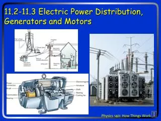
21.5 Electric Generators
21.5 Electric Generators. A sinusoidal emf is induced in the rotating loop ( N is the number of turns, and A the area of the loop):. (21-5). 21.6 Back EMF and Counter Torque; Eddy Currents.

21.5 Electric Generators
E N D
Presentation Transcript
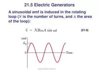
21.5 Electric Generators A sinusoidal emf is induced in the rotating loop (N is the number of turns, and A the area of the loop): (21-5)
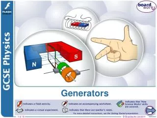
21.6 Back EMF and Counter Torque; Eddy Currents An electric motor turns because there is a torque on it due to the current. We would expect the motor to accelerate unless there is some sort of drag torque. That drag torque exists, and is due to the induced emf, called a back emf.
21.6 Back EMF and Counter Torque; Eddy Currents A similar effect occurs in a generator – if it is connected to a circuit, current will flow in it, and will produce a counter torque. This means the external applied torque must increase to keep the generator turning.
21.6 Back EMF and Counter Torque; Eddy Currents Induced currents can flow in bulk material as well as through wires. These are called eddy currents, and can dramatically slow a conductor moving into or out of a magnetic field.
21.7 Transformers and Transmission of Power A transformer consists of two coils, either interwoven or linked by an iron core. A changing emf in one induces an emf in the other. The ratio of the emfs is equal to the ratio of the number of turns in each coil: (21-6)
21.7 Transformers and Transmission of Power This is a step-up transformer – the emf in the secondary coil is larger than the emf in the primary:
21.7 Transformers and Transmission of Power Energy must be conserved; therefore, in the absence of losses, the ratio of the currents must be the inverse of the ratio of turns: (21-6)
21.7 Transformers and Transmission of Power Transformers work only if the current is changing; this is one reason why electricity is transmitted as ac.
21.8 Applications of Induction: Sound Systems, Computer Memory, Seismograph, GFCI This microphone works by induction; the vibrating membrane induces an emf in the coil
21.8 Applications of Induction: Sound Systems, Computer Memory, Seismograph, GFCI Differently magnetized areas on an audio tape or disk induce signals in the read/write heads.
21.8 Applications of Induction: Sound Systems, Computer Memory, Seismograph, GFCI A seismograph has a fixed coil and a magnet hung on a spring (or vice versa), and records the current induced when the earth shakes.
21.8 Applications of Induction: Sound Systems, Computer Memory, Seismograph, GFCI A ground fault circuit interrupter (GFCI) will interrupt the current to a circuit that has shorted out in a very short time, preventing electrocution.
21.9 Inductance Mutual inductance: a changing current in one coil will induce a current in a second coil. (21-8a) And vice versa; note that the constant M, known as the mutual inductance, is the same: (21-8b)
21.9 Inductance Unit of inductance: the henry, H. 1 H = 1 V·s/A = 1 Ω·s. A transformer is an example of mutual inductance.
21.9 Inductance A changing current in a coil will also induce an emf in itself: (21-9) Here, L is called the self-inductance.
21.10 Energy Stored in a Magnetic Field Just as we saw that energy can be stored in an electric field, energy can be stored in a magnetic field as well, in an inductor, for example. Analysis shows that the energy density of the field is given by: (21-10)
21.11 LR Circuit A circuit consisting of an inductor and a resistor will begin with most of the voltage drop across the inductor, as the current is changing rapidly. With time, the current will increase less and less, until all the voltage is across the resistor.
21.11 LR Circuit If the circuit is then shorted across the battery, the current will gradually decay away. where
21.12 AC Circuits and Reactance Resistors, capacitors, and inductors have different phase relationships between current and voltage when placed in an ac circuit. The current through a resistor is in phase with the voltage.
21.12 AC Circuits and Reactance The current through an inductor lags the voltage by 90°.
21.12 AC Circuits and Reactance In a capacitor, the current leads the voltage by 90°.
21.12 AC Circuits and Reactance Both the inductor and capacitor have an effective resistance (ratio of voltage to current), called the reactance. Inductor: Capacitor: (21-11b) (21-12b) Note that both depend on frequency.
21.13 LRC Series AC Circuit Analyzing the LRC series AC circuit is complicated, as the voltages are not in phase – this means we cannot simply add them. Furthermore, the reactances depend on the frequency.
21.13 LRC Series AC Circuit We calculate the voltage (and current) using what are called phasors – these are vectors representing the individual voltages. Here, at t = 0, the current and voltage are both at a maximum. As time goes on, the phasors will rotate counterclockwise.
21.13 LRC Series AC Circuit Some time t later, the phasors have rotated.
21.13 LRC Series AC Circuit The voltages across each device are given by the x-component of each, and the current by its x-component. The current is the same throughout the circuit.
21.13 LRC Series AC Circuit We find from the ratio of voltage to current that the effective resistance, called the impedance, of the circuit is given by: (21-15)
21.14 Resonance in AC Circuits The rms current in an ac circuit is: (21-18) Clearly, Irms depends on the frequency.
21.14 Resonance in AC Circuits We see that Irms will be a maximum when XC = XL; the frequency at which this occurs is (21-19) This is called the resonant frequency.
Summary of Chapter 21 • Magnetic flux: • Changing magnetic flux induces emf: • Induced emf produces current that opposes original flux change
Summary of Chapter 21 • Changing magnetic field produces an electric field • Electric generator changes mechanical energy to electrical energy; electric motor does the opposite • Transformer uses induction to change voltage:
Summary of Chapter 21 • Mutual inductance: • Energy density stored in magnetic field: • LRC series circuit:
Homework - Ch. 21 • Questions #’s 3, 4, 7, 18 • Problems #’s 1, 3, 5, 7, 9 ,11 ,13, 15