Timing RPCs
Timing RPCs. A.Schüttauf GSI. Outline. FOPI RPCs FOPIs RPC Electronic Anode Designs Future R&D Future Electronics Summary + Outlook. FOPIs Upgrade. 1 Super module (SM) 5 RPCs 16 strips/RPC. 1 Quarter. 6ns. FOPI RPCs. Test Setup 2000. FOPI RPCs 4 Gaps 0.3 mm 16 Strip/anode

Timing RPCs
E N D
Presentation Transcript
Timing RPCs A.Schüttauf GSI
Outline • FOPI RPCs • FOPIs RPC Electronic • Anode Designs • Future R&D • Future Electronics • Summary + Outlook
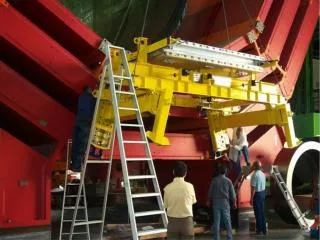
FOPIs Upgrade 1 Super module (SM) 5 RPCs 16 strips/RPC 1 Quarter
6ns FOPI RPCs Test Setup 2000 FOPI RPCs 4 Gaps 0.3 mm 16 Strip/anode 2/1 mm strip to gap 1 mm float glass 50 4 90 cm2 active. Lemo cables.
FOPI Results I Single hit tests Fragmented C12 beam MIP protons M.Petrovici GSI-Jahresbericht 2001 p.216
RPCs CDC Double hit t>110ps Mini RPC 4x5cm2 BUT !!!! CDC-matched single t>85 ps FOPI Results II Single Hit t>85 ps
6ns Xpos [cm] TOF [ns] TOF [ns] Xpos [cm] -source Anode C-Blocks C-Blocks Reflections ~12
2.6ns Xpos (cm) TOF (ns) TOF (ns) Xpos(cm) Solution K.Hildenbrand,V.Simion Excellent adaptation 50 ±1 We went thru a painful review of our counter impedance. Solution: Adapt your counter to 50 ±1
Q 4 gap RPC side view 150-200 ps correction Q only for walk Riegler et al. NIM in press Charge and # of Gaps GSI
RPC-FEE 4 ch. FEE-card Preamp + discriminator T/Q information. Gain ~ 200-250 Gain ratio T/Q ~ 2.5 High power ~ 1.6 W/ch Interface to detector is still lemo cables. GSI M.Ciobanu
TAC E>30 ps FEE + TAC RPC-Readout (TAC) GSI-ELEX R.Schulze.R.Hardel, K.Koch,E.Badua
New FEE+TAC t >30-35 ps p >20-25 ps GSI-ELEX R.Schulze.R.Hardel K.Koch,E.Badua GSI M.Ciobanu FEE 9.5 16 cm2 16 ch Gain 200 T/Q ~ 2 0.5 W/ch TAQUILA 9.5 25 cm2 16 TAC 16 ADC Zero Sup. GTB-SAM3
Pad Multi Strip Single Single Cell Anode Designs
Advantage-Disadvantage Pads : Advantage: Less reflections Rate Disadvantage: Counter consist mainly out of borders. High granularity needs more electronic channels Dead zones Multi strip Advantage: High granularity in or for low price. Disadvantage: Adaptation Reflections Single cells Advantage: Small Independent Disadvantage Price / m2 Infrastructure Efficiency Dead zones Single strip Advantage: Simple concept Disadvantage: Double hits Granularity Efficiency
Design R&D GSI Anode design: Varying strip counters 32, 64 Varying strip pitch Varying pad size and number Readout type Full differential counter 110 Single ended 50 Support structures: Self supporting Honeycomb structure Glass thickness Spacers (Fiber, rod) Detector interface Size: Quadratic counters Long counters ~2 m
Granularity for CBM CBM-TOF: Size120 m2 #Ch ~100000 Full system t < 75 ps Rate ~50-50000 Hz/cm2 Concepts: Different detectors types in low and the high rate environment. Low rate <2 kHz Pad anode Multi strip anode Single strip anode High rate > 2 kHz Pad anode Single cells Problem: Different counters may need different electronics. K.Wisniewski
Price: FOPI-RPCs 2/3 price electronics #Ch <10000 FOPI-FEE ~ 15 €/ch FOPI-TAC ~ 60 €/ch 75 €/ch #Ch =100000 7.5 M€ Here the ASIC design over head pays off. Why ASICs Power consumption: Fast preamps on standard RF-design need a lot of power. Typically 0.3 -1.5 W/ch. In an ASIC we can reach 10-30 mW/ch. Price/ch Power/ch Integration level Integration Level: The current FOPI-FEE is close to the limit of the conventional design, with 16 channel on 152 cm2
FEE-ASIC HD-GSI Boundaries: Signal rise time <200 ps Bandwidth 400 – 1000 MHz Gain 100-150 Time over threshold for walk Needed: # 8-16 ch Low power Cheap Existing CERN-ALICE 8 ch. CMOS process Current sensitive preamp. Gain ~ 100 Status: In test phase Questions: Which process CMOS or Bipolar ? Current or charge sensitive preamp ? Full differential design ?
TAC/TDC Digitization GSI-ELEX Problems: Price ~ 60€/ch Heat ~ 5 W/ch Integration TAC ASIC # 1 ch. t >10 ps R&D TAC/TDC ASIC # 8-16 ch t >20 ps Multi hit capability Questions: CMOS for TAC/TDC Bipolar or CMOS FEE Hybrid Analog-Digital ASIC
FOPI RPCs Multi strip anode RPC Single hit <70 ps Double hit <110 (to be proven) Reflections solved New FEE in test phase New TAQUILA in test phase R&D for CBM RPCs 10 groups involved in EU/INTAS proposals Sub-Projects: Counter design, FEE, TAC/TDC, DAQ Interface, Tests Details of organization/subtasks to be discussed/defined during working group session. Proposed tasks at GSI: Anode designs strips, pads. Readout type differential or single ended. FEE-ASIC TAC/TDC-ASIC Summary + Outlook