Download
1 / 72
720 likes | 759 Vues
Learn about solar cell operation, band gaps, efficiencies, LED characteristics, and more in this educational resource on photovoltaics experiments. Explore semiconductor materials and generation of photovoltage with practical demonstrations. Discover the LED as a photovoltaic cell and its applications.

E N D
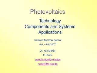
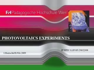
PHOTOVOLTAICS EXPERIMENTS IP EFEU LLP/AT-230/22/08 I.Hantschk/H.Fibi 2009 PH Wien – Photovoltaics Experiments
Photovoltaics Permission to use is granted on the following conditions: The use is for educational purposes onlyNo fees or other income is charged Appropriate reference to this source is made. Data sources are indicated except pictures and drawings having been taken by the authors respectively publishers. Updated for LLP/AT-230/22/08 Published by OStR. Mag.rer.nat. Hans Fibi & Prof. Ingrid HantschkUniversity of Education Vienna Grenzackerstraße 18 1100 ViennaAustria Phone: +436643833955e-mail: Hans210347@a1.net or johann.fibi@phwien.ac.at 2009 This project has been funded with support from the European Commission. This publication [communication] reflects the views only of the author, and the Commission cannot be held responsible for any use which may be made of the information contained therein. PH Wien – Photovoltaics Experiments
The Sun generates Electricity Thermocouple(Candle instead ofconcentratedsunlight) Solar Cell at work) PH Wien – Photovoltaics Experiments
Semiconductor intrinsic conduction traditional schedule PH Wien – Photovoltaics Experiments
Semiconductor Lattice of the diamond-type Because of defects in the crystal and at rising temperature - input of caloric energy - some electrons are set free - the crystal shows intrinsic conduction. Matter: Silicon, Indiumphosphide, Galliumarsenide, Cadmiumtelluride New: Compounds as III-V or II-VI type or organic compounds PH Wien – Photovoltaics Experiments
Doped Semiconductors PH Wien – Photovoltaics Experiments
Doped Semiconductors n p n p intrinsic (reverse) voltage There must be: A carrier – usually a crystal gratingn-layer – providing electronsp-layer – providing places for the electrons on travel PH Wien – Photovoltaics Experiments
Generation of Photovoltaics • For generating photovoltage, you need: • matter, from which photons are ableto dissolve electrons: Si, Ge,semiconducting compounds (InSb, InP, GaAs, GaAsP, CdS, CdTe). • Intrinsic potential difference being able to separate the electronsfrom the positive defective electrons. PH Wien – Photovoltaics Experiments
Generation of Photovoltage PH Wien – Photovoltaics Experiments
Generation of Photovoltage The band gaps are: Si...1,12 eVmaximum of sensitivity: red long wave limit: IR 1,1 mm above translucent Ge...0,7 eVGaAs...1,42 eVCdTe...1,5 eVGeS.....1,5 eVInSb...0,2 eV (IR) PH Wien – Photovoltaics Experiments
Generation of Photovoltage Efficiencies at 1 kW/m²: c-Si (crystal Si).....max 28 % practically 18 % mc-Si (multicrystal-Si)...16 % a-Si (amorphous Si)...13-17% PH Wien – Photovoltaics Experiments
The LED - forward and reverse biased Which of both LEDs is shining ? Change the poles of the battery(pole reversal). Which of the LEDs shines now ? Remove one of the LEDs.Measure the drop in voltage cross the LED. The LED is forward biased, it shines:U = .............. V The LED is reverse biased.U = ...............V If the LED is reverse biased, a high drop in voltageis to be found cross the LED. This picture allows you to find out the correct positioning of the LED symbol Forward voltage drop...measured at the forward biased lED, necessary to forcecharges passing the LED PH Wien – Photovoltaics Experiments
The LED - forward and reverse biased PH Wien – Photovoltaics Experiments
The LED as Photovoltaic Cell Measurement of the voltage generated by irradiation: light light Note, to whichpart of the spectrum the different LEDs are sensitive. The so generated voltage is called photoelectric voltage. PH Wien – Photovoltaics Experiments
The LED as Photovoltaic Cell The voltage depends on the gap betweenconductive and valence band. PH Wien – Photovoltaics Experiments
The LED as Photovoltaic Cell Relatively high Voltage, but... ....about no capacity !! PH Wien – Photovoltaics Experiments
The LED is used as PHOTODIODE The LED is connected into the circuitreverse biased!! Expose the LED to an intensive radiation. The intensity of current is I = .................... mA. Now vary the irradiance only a bit. In doing this observe the current´s intensity. The result is:....................................... Application: very sensitive exposure meter PH Wien – Photovoltaics Experiments
Resistance of a Solar Cell The solar cell is reverse biased. Do not use more than 3 DCV.Only use a little surface, if necessary cover the surface partially with a cardboard. If the solar cell is shadowed, it has a high internal resistance because ofa high drop in voltage. PH Wien – Photovoltaics Experiments
Resistance of a Solar Cell Direct sunshine: U = 0,55V, I = 0,74 AR = 0,8 Ohm Shadowed: U = 0,47V, I = 0,067 AR = 7 Ohm PH Wien – Photovoltaics Experiments
Resistance of a Solar Cell Solar Cells connected inseries, one of them beingshadowed bypass diode is necessary. Darkened: U = 0,11V, I = 0,0012 AR = 92 Ohm PH Wien – Photovoltaics Experiments
Open-Circuit-Voltage of a Solar Cell + + back side with connections Solar Cell DCV - 2 V The open circuit voltage is measured at different irradiances. Umax = ............ DCV You may draw a diagram now. PH Wien – Photovoltaics Experiments
Open-Circuit-Voltage of a Solar Cell shadowed: U = 0,47 DCV(scattered radiation) bright sun: U = 0,55 DCV darkened: U = 0,11 V(Infrared radiation) PH Wien – Photovoltaics Experiments
Calibration for Irradiance-Measurement Solar Cell d = 1 cm PH Wien – Photovoltaics Experiments
Calibration Solar Cell 1 cm² illuminated PH Wien – Photovoltaics Experiments
Thermo-Column (Moll) Thermosäule nach Moll Thermo-Column Empfindlichkeit (Sensitivity) 0,16 mV/mW Wellenlängenbereich (wavelenght) 150 nm – 15000 nm Innenwiderstand (Internal Resistance) 10 Ohm Einstelldauer (duration for measurement) 2-3 s Eintrittsfläche (sensitive area) diameter 34 mm Thermo-Column thermo-couples In series PH Wien – Photovoltaics Experiments
Irradiation Al, blackened temperaturemeasurement 0,01 K accurateness styrofoam Measurement of the total irradiance dQ (J) = e . c . m . dd e...absorption coefficient ~ 0,95 c...specific warmth, Al-0,89 kJ/kg.K m...mass-kg dd..temperature difference – K Measurements duration up to thermal balance PH Wien – Photovoltaics Experiments
Characteristic Lines of a Solar Cell PH Wien – Photovoltaics Experiments
Photovoltage mit: q..Zahl der je Sekunde pro Flächeneinheit der p-n-Schicht gebildeten Elektron-Loch-Paare L...Diffusionslänge D...Diffusionskonstante n0, p0: Gleichgewichtskonzentration der Elektronen bzw. Elektronenlöcher t...Lebensdauer der Elektron-Loch-Paare Sonderfall:DE = DL, LE = LL, n0 = p0: mit j = q.e PH Wien – Photovoltaics Experiments
V 25% 50% 75% 100% Conclusion: Photovoltage – Exposed Area Cover parts of the surface area and observe the voltage in any case ! The Solar Cell is directly connected to the voltmeter. (2 DCV) PH Wien – Photovoltaics Experiments
Short-Circuit-Current of Solar Cells The Solar Cell is directly connected to the ammeter. The intensity of the short circuit current is direct proportional to the irradiance. The short circuit current is measured at different irradiances. You may draw a diagram now. By this you can measure the illumination. PH Wien – Photovoltaics Experiments
Short-Circuit-Current of Solar Cells A A A A A A A Solar Cell / Exposed Area covered to 0%/25%/50%/75%/100%. The Solar Cell is directly connected to the ammeter. mA Despite the surface is totally covered current is to be measured.This demonstrates the influence of IR. Cover parts of the surface area and observe the intensity of current in any case ! 25% 50% 75% 100% PH Wien – Photovoltaics Experiments
Dependencies The Solar Cell is directly connected to an ammeter. Different Surfaces about the same voltage – only dependent onthe irradiance Short current´s intensity depending on theirradianceand proportional to the surface. The Solar Cell is directly connected to a voltmeter. PH Wien – Photovoltaics Experiments
Sensitiveness – Spectral Range 2 DCV Highest sensitiveness to red indicates Silicon. PH Wien – Photovoltaics Experiments
Sensitiveness – Spectral Range The Solar Cell shows the highest efficiency in the red part of the spectral range. This is an indicator for Silicon. PH Wien – Photovoltaics Experiments
connecting in series - + - + measurement gauge Connecting Solar Cells into Series Measure the open circuit voltage of any of the two solar cells:U1 = ............... V U2= ................ V Measure the short current intensity of any of the two solar cells:I1 = ............... mA I2= ................ mA Connect the solar cells into series. Measure now the open circuitvoltage as well as the short current intensity of both solar cells: U1 + U2 = ................. V I1 + I2 = ...................... mA Voltages are added, intensities remain the same. PH Wien – Photovoltaics Experiments
Connecting Solar Cells into Series PH Wien – Photovoltaics Experiments
mA / V Connecting Solar Cells into Series Cover one solar cell. This onecannot produce photovoltage. U = ............... V I = ................ mA The internal resistance of the clouded solar cell is rather high,so the current´s intensity goes tozero. The clouded solar cell blocks the current and therefore has to be bridged by an open-circuit-diode. PH Wien – Photovoltaics Experiments
Connecting Solar Cells into Parallel Measure the open circuit voltage of any of the two solar cells:U1 = ............... V U2 = ................ V Measure the short current intensity of any of the two solar cells:I1 = ............... mA I2= ................ mA Connect the solar cells into parallel. Measure now the open circuitvoltage as well as the short current intensity of both solar cells: U1 + U2 = ................. V I1 + I2 = ...................... mA Intensities are added, voltages remain the same. PH Wien – Photovoltaics Experiments
Connecting Solar Cells into Parallel PH Wien – Photovoltaics Experiments
mA / V Connecting Solar Cells into Parallel Cover one solar cell. This onecannot produce photovoltage. U = ............... V I = ................ mA The darkened solar cell is out of order, this deminishes the current. It has the effect of reducing the exposed surface area. PH Wien – Photovoltaics Experiments
Running an Engine U = ................. V I = ............... mA P = .............. mW The engine runs... ...fast ...slow ...not U = ................. V I = ............... mA P = .............. mW The engine runs... ...fast ...slow ...not U = ................. V I = ............... mA P = .............. mW The engine runs... ...fast ...slow ...not Run the engine at different illumination - sunlight, shadow, indoor. For shadowing you may use a grid. PH Wien – Photovoltaics Experiments
Running an Engine PH Wien – Photovoltaics Experiments
Efficiency h= F . A . Q fill factor...share of energy being transfered from the solar cell to the appliance. absorption ability, depends on material and frequency of radiation yield of quanta energy, abundance, to which photons solve electrons. For Si it is: h = 0,8 . 0,7 . 0,21 = 0,12 (12%) PH Wien – Photovoltaics Experiments
Efficiency PH Wien – Photovoltaics Experiments
Calculating the Efficiency / Engine´s Experiment • Measurement of the irradiance by means of a calibrated solar cell: • x W/m² • Dimensions of the solar cell (battery) used: • l = ................ cm, b = ................... cm • A = ........................ m² • Irradiance P:P = x . A = .......................... W • Measurement of the engine´s power: • U = ..................... V • I = ............. mA = ....................... A • P = U . I = ..................... W1 PH Wien – Photovoltaics Experiments
Calculation with EXCEL Open the table on your disc and calculate ! PH Wien – Photovoltaics Experiments
Linear increasing intensity of current Voltage shows „saturation“ The Characteristic Line Measured values... Calculate the resistance when being dark: IK = 2,6 mAU = 0,055 V / I = 0,17 mAR = 204 Ohm ...when being bright:IK = 610 mAU = 0,502 V / I = 496 mAR = 1 Ohm PH Wien – Photovoltaics Experiments
The Power Characteristic The I-U-characteristic of a Solar CellA = 10 cm x 10 cmirradiance 1000 W/m², d =25 oC I...Short CurrentU...Open-Circuit-Voltage Indicated...Power Maximum Max. power, if external resistance equals the internal resistance of the solar cell. PH Wien – Photovoltaics Experiments
Pmax The Power Characteristic Max. power at U = 0,35 V and I = 700 mA Pmax = 245 mW Problem was:adaption of the valuesof the external resistor PH Wien – Photovoltaics Experiments
The Power Characteristic Problem was:adaption of the valuesof the external resistor Caused by this:problematiccharacteristic power line PH Wien – Photovoltaics Experiments